Linear heat fire detectors. Linear thermal fire detector: types, classification, technical characteristics, installation, configuration and operation features Linear thermal thermal cable detector
There are many types of devices for early detection of fire sources that are part of the installations / systems of the fire alarm system, which, in turn, are elements. Various fire detectors are also integral parts of gas, water, powder, without which today it is impossible to operate as production facilities and public buildings.
In the overwhelming majority of cases, point PIs are used, which determine the appearance of factors for the occurrence of a fire source in a controlled area limited by its own technical characteristics, as a rule, having the shape of a circle or a sector. However, in many industrial, warehouse, public buildings / structures with a large height, width, length, they are not applicable, because this excludes their capabilities, application restrictions.
In such cases, for the protection of facilities, specialists of design organizations provide for the use of linear IP, which can record the appearance of heat, smoke on a straight section / area of the room, even of a significant length.
Linear security detectors designed to control unauthorized crossing of the perimeter, the active detection zone, are very similar in purpose, only to protect the property of citizens / organizations from theft.
Types of linear fire detectors
To them on the basis of the definition that sets the design standards for APS, ASPT; sounding that a linear fire detector (smoke, heat) is an IP that responds to signs of a fire in an extended protected area, there are two types of such technical devices:
- Smoke detector, linear (IPDL) is a product that transmits an infrared beam with a device / sensor, which is sensitive to the transparency of the air in a protected room / building. When smoke occurs that exceeds the set threshold value, the optical detector will be triggered, transmitting an alarm signal to the receiving equipment of the APS installations, the control and starting devices of the ASPT. In many ways, it is precisely due to the thin, straight line of the IR beam, the location of the transceiver devices exactly on the same axis, such types are called linear IP.

- In addition, they are divided into two types - two- or one-component systems. The first is the traditional layout of a product consisting of two devices: transmitting a continuous optical signal and receiving it on the opposite side of the room. The second is when the transmitting and receiving parts are made in a single housing, and the transmitted infrared beam is directed to a passive reflector / reflector, exactly fixed in place opposite the device. Such linear detectors with reflector are more modern devices that require lower costs for laying substation loops, setting up products.

- Heat detector linear (IPLT) also has several varieties according to the type of temperature-sensitive cable used in this product. They can be contact, electronic, mechanical or optical, while for all the main purpose is to fix the threshold or differential temperature increase along the entire length of the thermal cable. It is worth considering them separately.
- Contact. In them, thermosensitive elements consist of several conductors in fusible insulation.
- Electronic. They are based on changes in electrical current caused by heat. Here thermoelements are many sensors in a multicore cable.
- Mechanical. The sensing element is a metal tube filled with compressed gas, the pressure of which rises as the temperature of the outside environment rises, which is fixed by the sensor of the electronic unit, which transmits a signal to the device.
- Optical. They use fiber optic cable, physical characteristics which also change when heated.
For more information, see the video.
Among the line of models of products of linear both thermal and smoke power supplies from many manufacturing companies are found, designed to protect premises in buildings / structures with a high.
Many specialists from design organizations, fire brigades, installation companies believe that it is quite possible to refer to linear IP; because, although the active zone of detection of the factors of the origin of the fire source is sectoral, the main indicator is the detection range, which for some models is up to 80 m, and this is comparable to the technical characteristics of smoke linear MT.
Pros and cons of linear detectors
The main advantage of linear IP is the ability to protect those objects where the use of point detectors is difficult, if not impossible due to design features buildings / structures, technological process, specific installation locations in the premises:
- Smoke... Installation in buildings with large construction volumes, internal, undivided spaces, such as assembly and other workshops of various industries at industrial facilities, warehouse complexes, logistics centers, exhibition, sports facilities, as well as museums, architectural monuments, where the installation of traditional heating, smoke IP on ceilings for various reasons is impossible or unacceptable. In addition, IPDLs are more sensitive to black smoke and have a high response rate to the appearance of pyrolysis products in the air.
- Thermal... IPLT can be installed where installation of point analogs is impossible - in technological galleries, cable tunnels, ventilation ducts, etc. engineering communications buildings / structures in other areas that are difficult to access for regular access / maintenance; and also for the protection of various equipment, even if the surrounding air environment is characterized by constant high dustiness, gas content, humidity, chemical aggressiveness.
- Flame detectors set to protect technological equipment located on the outdoor sites of industrial enterprises, incl. for work in harsh climatic conditions.
The disadvantages of linear detectors include the high cost of the set, which, however, pays off due to the fact that one product replaces several, or even more than a dozen, smoke, thermal power supplies based on the protected area of the room.

Varieties of linear detectors
Among the products sold today on the market of component parts for APS systems, the following models should be distinguished, characterized by good technical characteristics, reliability, ease of maintenance, maintainability:
- IP-104 / IPLT from the FlameStop company (Moscow) with a possible length of up to 3 (!) Km. Temperature range of operation from + 68 to 185 ℃. Thermal cable - twisted pair with a steel core coated with copper and tin. The main sheath is PVC, protective for various modifications - nylon (for outdoor installation, aggressive environments), polypropylene (for chemically active zones), in a steel braid - to protect against damage. Resistant to external temperatures up to + 125 ℃. Diameter - from 3.6 to 4.5 mm, depending on the outer shell. Weight - up to 20 kg / 1 km. Protected against electromagnetic interference.
- IP-104 "Granat - thermal cable" manufactured by the company "Spetspribor" (Kazan). The maximum length of use is up to 2 km. The response temperature is from 68 to 180 ℃. The maximum width of the protection zone is up to 7.6 m, the recommended width is up to 5 m. The outer diameter is 5 mm.
- IPLT XCR from Pozhtekhnika Group of Companies (Moscow). The used IP length is up to 1220 m. The outer diameter is 4 mm. Outer shell made of fluoropolymer resistant to aggressive chemical environments.
- Thermal cable PHSC-155-ECP from Protectowire. The length of the train is up to 2 km. Diameter - 4 mm.
- IPDL D / II-4R. The most common fire detector of this type, produced for more than two decades by NPF Poliservice from St. Petersburg, consisting of two blocks - an IR transmitter and a receiver. Operating range - up to 150 m. Protection - IP
- IPDL-52M manufactured by IVS-Spetsavtomatika. One-component linear detector, which includes a transceiver unit, made in one housing, a reflector. Range - up to 80 m, width of the protection zone - up to 9 m.
- IP 212 "Trion-L2-MK" "Company SMD" is intended for the protection of fire and explosion hazardous premises. Controlled area - up to 900 sq. m. Protection - IP
- SP 212-125 (6500R) from the SensorSystem company. One-piece device of the new generation. Range of work - up to 70 m. Protection - IP
- Arton-DL. Linear one-component smoke power supply with a range of up to 100 m.
- IPDL-EX. Manufacturer - NVP "Bolid". Two-piece device designed for installation in hazardous areas. The range of this linear detector is up to 150 m.
In addition to these models / brands, many more are presented on the fire-fighting equipment market various products, so for optimal choice it is necessary to proceed from the characteristics of the premises of buildings / structures, outdoor installations / equipment, the upcoming conditions of installation, operation and further maintenance.
Linear fire detectors: heat, gas, combined
Indoor installation and installation rules
The installation standards for linear IP are set out in SP 5.13130.2009, in particular, in relation to IPDL:
- The placement of detectors should be carried out in such a way that there are no objects between the devices, even temporarily.
- Installation of linear fire detectors in a room with a height of more than 12 m should be carried out in two tiers.
- Installation of IPDL when protecting a zone / room with two or more products should be carried out so that the distance between them is no more than 9 m, from the wall - no more than 4.5 m.
The designation of a linear fire detector depends on the type of IP - heat, smoke, flame.
Laboratory studies have established that linear detectors are significantly superior in sensitivity and response speed to both thermal and smoke traditional devices.
As a rule, this does not mean at all that it is preferable to choose IPLT / IPDL instead of point PI. Each type has its own tasks, due to both technical characteristics and the upcoming places of installation, operation and maintenance, which is always taken into account when developing design and estimate documentation, including the cost of various products.
In practice, at large facilities, several types of fire detectors, both point and linear, are used, which is facilitated by the ability to connect them to the same control and monitoring devices, for example, manufactured by the company "Bolid".
The main elements of a fire alarm system are devices that detect a fire by any of its signs, - fire detectors. The efficiency of the entire fire alarm system as a whole largely depends on the quality of their work.
S.V. Shevchenko
Head of the technical department of ASK LLC
Currently, not every facility in Russia is equipped with an efficient automatic fire extinguishing, and if the building is old, then such a system cannot be built without its capital alteration. In such cases, the main burden of performing tasks related to the timely elimination of a fire falls on the fire detection system or, in other words, the fire alarm system, the main element of which is fire detectors. It is known that in many cases smoke detectors are the most effective, but sometimes their use is difficult or simply impossible.
Thermal fire detectors
Heat detectors react to temperature changes environment... They are installed when:
- in a controlled volume, the structure of the materials used is such that the dominant factor in a fire is the release of heat (for example, when burning flammable liquids);
- the spread of smoke is difficult due to external conditions (low temperature, high humidity, etc.);
- the air contains a high concentration of any aerosol particles that are not related to combustion cycles (for example, exhaust gases from running car engines, construction dust, industrial dust or mist).
Maximum heat fire detectors are often used - devices that give an alarm in case of exceeding a predetermined fixed temperature value in advance. Usually it is from +54 to +70 ° С. When heated, the electrical circuit is broken (or closed), due to which an alarm signal is generated. Detectors of this type include domestically produced devices, such as IP-105 and similar ones.
High-performance point heat detectors are inexpensive. They are triggered when a certain temperature is reached at the protected object and do not allow detecting a fire at the initial stage of its development. For this reason, at present, the production of the cheapest heat fire detectors of maximum action has been sharply reduced and their use is limited.
More complex maximum thermal fire detectors are equipped with a temperature-sensitive semiconductor element that forms a closed electrical circuit with a negative temperature resistance, to which a certain potential difference is applied. As the temperature rises, the resistance of the circuit drops, and more current begins to flow through it. The current value is monitored and an alarm is generated if the set value is exceeded.
Linear heat fire detectors
Even more interesting is the use of linear heat fire detectors, since linear detection provides unique advantages when used in places with difficult access, places with increased pollution, dust, aggressive or explosive environments. In addition to the above cases, these detectors are used where long-distance cable channels are stretched at large industrial enterprises, ore conveyors have been installed at mining and processing plants, coal-fired boilers are operating, baggage supply lines have been laid in airport terminals, etc.
The first linear fire detectors were detectors distributed along the length of the object, which generate a warning or alarm signal when the air medium heats up to a temperature corresponding to the melting of the insulation of the metal conductors of the thermal cable.
The most commonly used linear heat detectors in Russia
Thermal cable Protectowire (USA)
Such detectors, distributed along the length of the object, include the American-made Protectowire thermal cable.

Operating principle
When the temperature threshold is reached, under the influence of the pressure of the conductors, the insulating coating of the heat-sensitive polymer is destroyed, which allows the conductors to come into contact with each other. This occurs at the first point of overheating on the thermal cable route. To trigger the signal, you do not need to wait for the heating of a section of a certain length. The Protectowire thermal cable is a maximum heat detector, and therefore allows you to generate a pre-alarm and alarm when the temperature threshold (+68.3 ° C or +93.3 ° C) is reached at any point along the entire length of the cable. This thermal cable is a single continuous sensor and allows you to accurately determine the source before the appearance of fire or smoke. heating anywhere along its entire length.
The disadvantages of such a cable include the fact that it is not a temperature-tunable system. In addition, having detected overheating, the fusible steam is closed and "dies". In addition, the detectors do not distinguish between fire and short circuit.
More modern linear fire detectors are devoid of these disadvantages, but each of them has its own characteristics.
IP-102-2x2 system (Russia)
Multipoint heat fire detector IP 102-2x2 Designed to work in fire alarm and fire extinguishing systems together with control and monitoring devices that ensure work with current-consuming fire detectors.
Principle of operation and characteristics
The sensitive element of the DPT detector generates a signal (thermoelectric power station), the value of which is proportional to the rate of increase in the air temperature at the location of the sensor. According to the accepted classification in NPB 76-98 and NPB 85-2000, the detectors are differential.
In the interface unit (BC), 2 detector response thresholds can be set: 5 ° C / min and 10 ° C / min.
The inertia of the detector at a temperature rise rate of 5 ° C / min. is Tav = 1 25-130 s. At a temperature rise rate of 30 ° C / min. response time is Tav = 20-40 s.
Structurally, the thermoelectric fire detector is an electric two-wire twisted pair cable in a fluoroplastic sheath.
Composition
IP-102-2x2 includes:
- interface unit - BS;
- thermoelectric multipoint fire sensor - DPT;
- thermoelectric point fire detector (hold) - DPT-T;
- switch box - KK;
- manual contact fire detector - IPR-K;
- thermal contact sensor - DTK 1.02 (+70 ° C), DTK 2.02 (+90 ° C);
- final control device - UKK.
The detector can be used in rooms with conventional and aggressive environments, and at facilities with explosive zones. however, it should be noted that this detector is highly undesirable to use in rooms where there is significant temperature fluctuations, as this can lead to false alarms.
Transafe ADW 511 system (Germany)
Transafe ADW 511 is a linear thermal fire detector with threshold and differential temperature control.
Principle of operation
The principle of operation of the system is based on the volumetric expansion of the gas during heating and the associated increase in pressure in the pneumatic chamber. The temperature at which the detector is triggered is programmable. The system has a multiple effect, when it warms up, it gives an alarm signal, and when it is turned on again, it is ready for work.
Composition
Composition The system includes:
- sensor tube (SENSTUBE);
- detector unit (with control unit).
A pressure sensor constantly monitors the pressure in the sensor tube. The sensor signals are evaluated by a micro-cycler. The differential component is processed electronically.
If the pressure in the sensor tube rises sharply in a short time, the ADW 511 detector issues an alarm.
Interference due to, for example, weather conditions (slow pressure changes with temperature fluctuations), or pneumatic shock caused by high intensity road traffic in the tunnel are filtered out.

Self-control
The test motor with the pump increases the pressure in the sensor tube to the specified value at a specified interval. If, for example, due to leakage or damage to the sensor tube, the value received by the sensor does not correspond to the specified value, a fault signal is generated.
Minimum sensor tube length- 20 m.
Maximum permissible length- 80 m.
Longer sensor tube lengths are not standard and should be discussed with the manufacturer.
Alarmline LHD4: (Germany)
The system has the following characteristics:
- can quickly change the response temperature on the control unit;
- does not "die" - upon detecting overheating, it issues a signal; after resetting and then turning on the voltage, the system is again ready for operation;
- "distinguishes" a fire from a short circuit; constantly conducts self-tests to detect open circuit or short circuit;
- can work both autonomously and together with any control panel using normally closed / open contacts;
- in case of burnout, only the burned-out area is easily replaced, and not the entire cable;
- easy to install, since its mechanical flexibility allows the sensor to follow all the bends of the monitored area, economical, low maintenance, easy to start up. In addition, the system is resistant to mechanical and chemical influences, corrosion, moisture, dust. It is suitable for use in hazardous areas. The system can be easily extended in length.
Composition
The Alarmline LHD4 system consists of two elements:
1. A self-healing sensor cable that returns to normal operation after being in an overheated zone and even after a short time in a fire. The sensor cable is an elongated thermistor that detects temperature changes along its entire length.
2. The signal conditioning unit is a linear heat detector interface module. If necessary, it can be installed at a distance of up to 300 m from the sensor cable, using a section of fireproof cable to connect the system components.
How the system works
With an increase in temperature, the value of the parameters of the electrical resistance changes. The formed loops of the sensor cable, which means it decreases, and this change is recorded by the LHD4 detector. This activates the alarm at the set level of the response temperature. Temperature changes are recorded along the entire length of the cable, the range of sensors is up to 300 m.

The sensor cable consists of 4 insulated copper wires. A special polymer with a negative temperature coefficient is used as an insulating material. The wires are intertwined and protected by an external fire-resistant polymer sheath. The processing unit continuously monitors the insulation resistance of the conductors, which depends on the ambient temperature. When the insulation reaches a certain temperature set in the processing unit, the latter activates an alarm. This method temperature control allows detecting local overheating of the sensor cable in any of its sections, and a less significant rise in temperature over an extended section. The temperature threshold of operation is set depending on the length of the thermal cable. The processing unit monitors the presence of an open or short circuit in the sensor cable and generates a "Fault" signal if the cable is broken.
Summing systems
A distinctive feature of the Alarmline (Germany) and IP 102-2x2 (Russia) systems is the ability to add up the fire factor (temperature) controlled by the thermal cable along the length. It is known that during combustion, warm air masses rise in the form of a rather thin vertical jet above the fire (the divergence angle of the warm air jet is usually 10-20 °). At a height of 9-12 m, warm air from the fire is mixed with upper layers cold air, which leads to a significant expansion of the air stream in the horizontal direction and to a decrease in its temperature. For this reason, fire detection at high altitudes with spot heat detectors is ineffective.
In view of increasing production using expensive equipment and increasing the number of technological personnel at enterprises, it is often necessary to take care of the safety of people and technological equipment. Currently, in connection with the tightening of the rules for the construction of security systems, one often has to think about the use of one or another kind of system.
This article will consider an innovative solution in the field of fire safety - a device presented in the form of a cable.
A linear fire detector, another name for a thermal cable, is a device capable of detecting temperature changes in the section in which it is laid, in cases where it is impossible to install another kind of fire detectors.
Linear fire detector is a pair of conductors isolated from each other with heat-sensitive insulation, clad in an additional protective insulating layer.
Operating principle.
The principle of operation is as follows, when a fire or overheating occurs in the area where the thermal cable is used, the insulating layer of each conductor is disturbed under the influence of the threshold temperature, while the conductors are closed in separate or several areas. The control device decides to change the state at the control object.
Classification of the thermal cable according to the types of applied external insulation,
which significantly affects the use of the detector in specific environmental conditions:
- EPC type thermal cable, the insulation of which is considered the most versatile insulation made of PVC material, which allows it to be used in industrial and civil construction. The sheath provides good flexibility for cable routing at low temperatures. This ensures the proper fire resistance and moisture resistance.
- The EPR type thermal cable has a polypropylene outer sheath significantly increases the fire resistance and does not spread the effect ultraviolet radiation environment. Typically used in environments with aggressive chemicals, it is not subject to abrasion. At the same time, it functions reliably in conditions of high ambient temperatures.
- Thermal cable type XLT, the insulation of which is an insulating material made of polymer in the highest possible way capable of withstanding extremely low temperatures. the main purpose of this kind of isolation is the use of the detector on open areas, in the conditions of the Far North, in refrigerators and freezers.
- The TRI type thermal cable has similar EPC insulation properties, but the only unique difference from other cables is the TRI (TRI-Wire) cable is capable of producing two signals "Pre-alarm" and "Fire", depending on the installation.
- Thermal cable type XCR literally includes all of the above types of sheaths. High quality fluoropolymer casing, specially designed for special purpose objects, with reduced smoke and gas generation, mechanically abrasion resistant, with high resistance to low temperatures. As well as the EPR casing, it withstands aggressive chemical influences. active substances and ultraviolet exposure. And the possibility of using at low temperatures allows you to make similarities with the XLT type detector. The quality of the shell makes it possible to emphasize the versatility of the insulation material used.
Thermal cable classification by operating conditions
consider the following figure below, which will clearly demonstrate the ability to use one or another insulation in various environmental conditions.
Thermal cable classification by temperature conditions.
In the figure, you can see the cable model and the corresponding response temperature, in the operating temperature range.

The advantage of using a linear fire detector:
The thermal cable is highly sensitive to temperature changes along its entire length;
The presence of several temperature modes of operation due to the manufacture of devices of various types of manufacture;
Resistance to environmental conditions;
High resistance to low temperature conditions of the environment;
Low cost and simple solutions installation of the system, reduced operating costs.
System design principles:
The work is based on the principle of working with normally open contacts, therefore the monitoring device must have the feature of monitoring the closure of the communication loop $
It must be taken into account that when choosing this detector, it is necessary to take into account its internal resistance due to the long thermal cable, 1 Ohm per 1.5 m, which subsequently may affect the length of the thermal cable line in a given area;
When choosing this system in a protected area, it is worthwhile to be guided by the calculation of the possible resistance of the thermal cable and evenly distribute the total length in the area into several uniform sections, otherwise a cable section longer than 2000 m can lead to a false operation of the system;
Installation must be carried out in a single section, avoiding branching, to make division into zones, which are due to the determination of the source of the fire in one place or another;
When planning the cable laying, take into account the norms and requirements for cable laying.
Further, we will consider mounting devices that are used in security and fire alarm systems using a linear fire detector, based on equipment supplied by Protectowire, approved by VNIIPO EMERCOM of Russia.
Mounting components.
Mounting area box ZB-4-QC-MP tight connection of a linear detector and a communication loop. The design of the box allows to ensure reliable protection of the connecting unit from external environmental influences, contributes to ensuring a high-quality connection in a wide range of operating temperatures.
The example of application considered in the figure below shows that the contact connectors enclosed inside the box, with this use, allow adequately ensuring the connection of the thermal cable and the communication loop, as well as additional resistance, ensuring its integrity.

Ferrule SR-502
Its main purpose is to ensure the sealing of the cable entry into the mounting zone box ZB-4-QC-MP. A set-up coupling made of steel elements and O-rings allows you to get a reliable tight connection with the cable and the box, while not damaging the temperature-sensitive sheath of the cable cores.
Fastening devices.
Designed for fast, reliable and at the same time safe installation, the mounting elements allow you to gradually fix the cable during the pulling process, while ensuring the integrity of the thermal cable.
The fasteners presented below allow installation without additional stretching and squeezing of the cable insulation.
WAW clamp 
the appearance of the device allows you to guarantee a simple and reliable fastening the detector cable to the surfaces on which it will be laid. The principle of use lies in the fact that inside the clamp, the material of which, depending on the laying conditions, can be used of two types, the cable is placed and without pressure on the outer sheath it is clamped.
According to the type of material used, the clamp can be of two types: nylon (WAW-N) and polypropylene (WAW-P). Polypropylene clamps are suitable for use in high temperature environments, and nylon clamps for low temperature environments down to -40 ° C, and + 88 ° C, respectively, for polypropylene.
There are no peculiarities of installation on straight sections, but in the corners there is a shift of the installation point of the fasteners inside the cable bend by 1.3-2 cm from the intersection of the cable lines, after fixing on straight sections.
Also, for straight sections, more primitive fasteners such as OHS are applicable.
Linear Clamps OHS 
They are used to mount a linear fire detector in straight sections, as recommended by the manufacturer, between WAW clamps, while providing basic support for the detector.
 The OHS-1 clamp is made of galvanized steel, which justifies its use for indoor use, and the OHS-1/4-SS clamp is made of steel, which justifies its use for outdoor installations.
The clamp is fixed with any fastener (bolt, screw, hairpin, etc.).
The considered mounting fasteners allow fastening the thermal cable on a plane, but as a rule, during installation work, it is not always possible to perform work only on a plane, or it is not possible to install a clamp on it, you have to hang the detector in places from a building structure, where it will not be possible to fasten it according to one or the other Other considerations, considered earlier by the methods, resort to the use of clamps, which, without further disrupting the integrity of the building, will allow the cable to be laid.
BC series clamp set 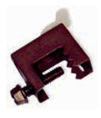
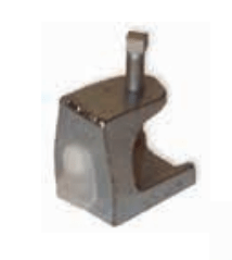 are used for laying the detector to building structures, without violating its integrity, and reasonable use of labor costs and installation time. They find applications when installing a thermal cable on cable runners, organized in trays, on metal structures, fachferkovy structural elements, etc.
The principle of fastening is that the BC-type clamp is fixed to the structure, and the thermal cable is already attached to it through the WAW-type clamp.
According to the place of use of the clamp, there are two types of clamps.
Clamp BC-2, material steel, used for laying the thermal cable indoors. 
Clamp BC-3, galvanized steel, is used for mounting the thermal cable on external structures. 
Adhesive type mounting kit 
in cases where it is not permissible to produce mechanical fastening, a temperature conditions and environmental conditions allow special requirements fasteners are used to the material, consisting of an assembly platform and a cable tie, which is glued onto a specialized industrial glue, which ensures the speed of installation and ease of work.
 To ensure the displacement of the thermal cable relative to the attachment point, use L-shaped mounting bracket RMC... L-shaped holder, at the end of which the WAW clamp or push-button latch has five holes for adjusting the offset distance. Like all previously discussed fasteners, this holder is made either of sheet steel or stainless steel, which makes it possible to use it both indoors and outdoors.
Mounting clamps CC-2. 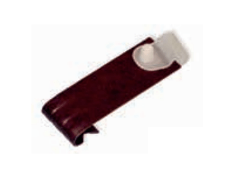
They are a composite system of fasteners that allows you to quickly and conveniently mount a linear fire detector along a cable tray with direct attachment to the tray. A typical "Caddy" clamp has a specific bend at one of the edges, which allows it to catch on the edge of the cable tray and securely hold it when hanging a thermal cable on the other of its edges, fixed by means of a snap fastener or a WAW clamp.
 For these purposes, the manufacturer produces two modifications of clamps for a tray with a thickness of 1.6-4.0 mm and a tray with a thickness of 4.0-6.0 mm, models CC-2N and CC-2W, respectively.

By using another clamp of the "Caddy" type, it is possible to fasten to the thicker elements of the cable tray in the same way.
Mounting clamps CC-10. 
Similar in principle of operation with clamps type CC-2. In addition to all the above, this type of clamp has the possibility of additional mechanical action for attaching the clamp to the tray, when using a bolted connection, in this case the clamp is recommended for mounting a linear fire detector in places subject to vibration.
 Fastener modifications are presented in two types:
CC-10N are used for trays with a wall thickness of 3.2 - 6.4 mm;
CC-10W is used for trays with a wall thickness of 7.9 - 12.7 mm. 
A less complicated, but also functional way of attaching a thermal cable may be possible with such products.
Mounting clip HPC-2. 
Resistant to UV radiation of the environment and having a bracket that allows you to hook the fastening lock to the material with a thickness of 1.5 - 6.4 mm, this clamp will allow you to install a linear fire detector without additional labor. The thermal cable is inserted into the clamp, which is attached to the structure corresponding to the purpose. Material - nylon. 
 With the same simple fastening method, it is possible to install a thermal cable using clamps.
Clamps PM-3. 
When laying a linear fire detector along sprinkler fire extinguishing systems, it was necessary to solve the problem of suspending a thermal cable to a pipe line, for which such hotuts were introduced.
The clamp-in-clamp system allows one clamp to fasten the fastening element itself, and the second one attracts the thermal cable, while there is no contact between the detector and the pipe, and most importantly, the cable compression site is not overtightened, and the inner insulating layer of the conductors is not disturbed. 
Nylon clamps are used at temperatures between -40 ° C and +85 ° C, while the installation temperature must not be below 0 ° C.
All of the above, in one way or another, refers to one installation method. Next, we will consider the method of laying on a string using a supporting cable.
Ncarrying trwasp 
An exclusive method of supplying a linear fire detector is that the carrying cable is already integrated into the detector. The stainless steel strands are located directly under one outer braid. The cable wraps around threads with a period of 0.3 m. The cores give the cable additional rigidity, which will allow it to be used in places where it is not possible to make fastenings in the usual way. 
The installation method is very clear, consists in the fact that the ends on the straight section of the fire detector are attached to fixed parts or lugs and tension is made with the help of a lanyard.
The length of such a section should not exceed 76 m, otherwise the cable may break. 
Also, to prevent the breakage of the thermal cable throughout the area of use of the linear fire detector, support elements are installed. The frequency of use of such elements is determined by the operating conditions, which is shown by practice for outdoor use, it is recommended to use the element more often in order to provide support and distribution of the load, from ice, snow load over the entire length of the thermal cable.
Linear heat detector (thermal cable) manufactured by Protectowire (USA) is a cable that allows you to detect the source of overheating anywhere along its entire length. The thermal cable is a single continuous sensor and is used in cases where the operating conditions do not allow the installation and use of conventional sensors, and in conditions of increased explosion hazard, the use of a thermal cable is the optimal solution.
The Protectowire Linear Heat Detector consists of two steel conductors, each with a thermosensitive polymer insulating sheath. Coated conductors are twisted to create mechanical stress between them, then covered with a protective sheath and braided to isolate them from harsh environmental conditions.
The principle of operation of the thermal cable
The principle of operation of the thermal cable: when the threshold temperature is reached, under the influence of the pressure of the conductors, the insulation coating of the heat-sensitive polymer is destroyed, allowing the conductors to come into contact with each other. This occurs at the first point of overheating on the thermal cable route. To trigger the signal, you do not need to wait for the heating of a section having a certain length. The Protectowire thermal cable is a maximum heat detector and therefore allows you to generate an alarm when a temperature threshold is reached at any point along the entire length of the cable.
Technical characteristics of the Protectowire thermal cable:
- High sensitivity all over
- Four temperature ranges
- High resistance to humidity, dust, low temperatures and chemicals
- Indispensable in hazardous areas
- Easy to install and set up
- Economical, no operating costs
- If necessary, extensions are simply added to the system
- Does not require maintenance. Expected service life over 25 years
Currently, there are several types of Protectowire thermal cable, differing from each other in the model type and the material from which the outer protective braid is made, for use in a wide variety of environmental conditions.
Criteria for choosing a thermal cable model for various temperature ranges:
| Temperature range: | ||||
| Basic | Intermediate | High | Ultrahigh | |
| Response temperature: | 68.3 ° C | 87.8 ° C | 137.8 ° C | 180 ° C |
| Minimum ambient temperature: | -44 ° C | |||
| Maximum ambient temperature: | up to 37.8 ° С | up to 65.6 ° C | Up to 93.3 ° C | up to 105.0 ° C |
| Standard, multipurpose: | PHSC-155-EPC | PHSC-190-EPC | PHSC-280-EPC | PHSC-356-EPC |
| Abrasive and chemical resistant: | PHSC-155-EPR | PHSC-190-EPR | PHSC-280-EPR | PHSC-356-EPR |
| Combined, for two response temperatures: |
PHSC-68/93-TRI: Low pre-alarm temperature 68.3 ° C; high pre-alarm temperature 93.3 ° C |
|||
| Special, for low temperatures down to - 57 ° С: |
PHSC-135-XLT: Maximum set temperature environment up to 37.8 ° C; Response temperature 57 ° С |
|||
The main areas of application of the Protectowire thermal cable:
The Protectowire thermal cable is used as a fire detector in fire alarm and fire protection systems. The use of a thermal cable is optimal and effective in various hard-to-reach, hazardous, industrial areas. Buy thermal cable you can in our company -.
 Objects for which the use of a thermal cable is recommended:
cable routes;
tunnels;
warehouses;
power plants;
escalators;
elevators;
open storage racks;
conveyor conveyors;
elevator shafts;
garbage chutes;
dust collectors;
flights of stairs;
bridges and piers;
hangars for aircraft;
other facilities in the petrochemical, coal mining, steel, transport and explosive industries.
The thermal cable can be easily added to any automatic fire alarm system. For this, it is necessary to have a monitoring device with dry contact inputs. The thermal cable has a Russian fire safety certificate and its use on the territory Russian Federation regulated by NPB 88-01.
The main areas of application of the thermal cable
The PHSC thermal cable is intended for use on objects with a large length and area, tunnels, in places where it is difficult to use traditional fire detection means. It is a fire heat detector that allows you to determine the distance to the point of its activation with an accuracy of a meter.
The PHSC thermal cable has found wide application in the oil and gas industry, chemical production and metallurgy. A significant feature of the thermal cable produced by Protectowire (Pozhtekhnika is the official Russian distributor) is its operating conditions: the PHSC linear heat detector can be used in areas of high pollution, humidity, exposure to chemicals, low temperatures, the thermal cable can be laid in the immediate vicinity of equipment requiring a fireman / temperature control.
Typical objects on which the thermal cable is used: cable routes, tunnels, subways, hangars for aircraft, conveyor conveyors, elevators, transformer substations, electrical equipment, large storage areas, liquid fuel storage facilities, storage refrigerators, tower cooling towers of nuclear power plants and thermal power plants, piers, covered bridges, garages, storage tanks.
Norms for laying a thermal cable according to NPB 88-2001
- Linear heat detector - the thermal cable must be laid in direct contact with the fire load.
- The thermal cable can be installed under the ceiling above the fire load in accordance with the norms for the placement of heat detectors. See the table below.
- Priority should be given to the technical characteristics specified by the manufacturer.
- The distance from the thermal cable to the overlap must be at least 15 millimeters.
- When used on racks, laying on the upper tiers is allowed.
A detailed description of the Protectowire PHSC thermal cable
A linear heat detector (thermal cable) manufactured by Protectowire (USA) is a cable that allows you to detect a source of overheating anywhere along its entire length. The thermal cable is a single continuous sensor and is used in cases where the operating conditions do not allow the installation and use of conventional sensors, and in conditions of increased explosion hazard, the use of a thermal cable is the optimal solution. The Protectowire Linear Heat Detector consists of two steel conductors, each coated with a thermosensitive polymer. Coated conductors are twisted to create mechanical stress between them. The outside of the conductors is covered with a protective sheath and placed in a braid to protect against adverse environmental conditions. The principle of operation of a thermal cable is based on the destruction of an insulating coating made of a thermosensitive polymer under the influence of the pressure of the conductors when the threshold value of the ambient temperature is reached. In this case, the conductors are closed among themselves. This can occur at any point of overheating along the entire length of the thermal cable. For the cable to operate, it is not required to wait for the heating of a section having a certain length. The Protectowire thermal cable allows you to generate an alarm when the temperature threshold is reached at any point along the entire length of the thermal cable.  The structure of the PHSC series Protectowire thermal cable
Currently, there are five types of Protectowire thermal cable, differing from each other in the model type and the material of the outer protective sheath, which makes it possible to operate the thermal cable under various environmental conditions.
EPC- EPC type thermal cable has a strong extrusion outer protective PVC sheath, which provides reliable protection of the cable under various environmental conditions. The thermal cable of this series is versatile and well suited for both industrial and commercial use. The sheath of the heat cable is fire and moisture resistant and
retains good flexibility when used at low temperatures.
EPR - EPR type thermal cable has a strong fire-resistant outer sheath made of polypropylene, resistant to UV radiation. Created for wide application in industry and is characterized by high elasticity, resistance to chemically aggressive media, abrasion, atmospheric conditions and reliable operation when high temperatures ah environment.
XLT- XLT type thermal cable has a polymer outer sheath and was specially designed for use in extreme low temperatures... This sheath allows the use of this cable in refrigerated warehouses, commercial freezers, unheated warehouses, as well as in the harsh climatic conditions of the North.
TRI- thermocable type TRI (TRI-Wire ™) is a unique linear heat detector that allows you to receive two trigger signals (“Prealarm” and “Fire”) depending on the set temperature thresholds. The thermal cable is enclosed in a PVC sheath and has characteristics similar to the EPC series.
XCR- new on Russian market... The XCR series thermal cable is enclosed in a high quality fluoropolymer outer sheath. This type The detector was specially designed for objects, for the protection of which it is necessary to use reliable, high-tech and environmentally friendly equipment. Main feature The XCR series thermal cable is a fluoropolymer flame retardant jacket with reduced smoke and gas emission, providing the highest mechanical abrasion resistance over a wide temperature range. The sheath also protects the thermosensitive polymer from a wide variety of acids, alkalis, organic solvents, and simple gases. In addition, the casing is resistant to sunlight (including UV radiation), as well as to various weather conditions.
This type of thermal cable allows use at extremely low temperatures and demonstrates the best performance in comparison with other types.
Benefits of using Protectowire thermal cable:
- High sensitivity along the entire length of the detector.
- Five different temperature ranges.
- High resistance to moisture, dust and chemicals.
- Indispensable when used at low temperatures.
- Simplicity and ease of installation.
- No operating costs (no maintenance required).
- Service life over 25 years.
- The entire range of Protectowire thermal cables used has a RF fire safety certificate, as well as FM and UL certificates.
Electromechanical characteristics of the Protectowire thermal cable.
Resistance * ~ 0.656 Ohm / m
Capacitance * ~ 98.4 pF / m
Inductance * ~ 8.2 μH / m
Dielectric strength = 500V (AC), 750V (DC)
Maximum operating voltage = 40VDC
Outer cable diameter (EPC, EPR, XLT, XCR) ~ 4mm
Cable outer diameter (TRI) ~ 4.5mm
* - Electrical characteristics indicated for twisted pair conductor

Temperature modes of the PHSC thermal cable

PHSC thermal cable classification by temperature regime work
Optical thermal cable Protectowire
Currently, the shutdown of data processing systems is complex technological processes caused by overheating and fires, cause colossal losses to the economy of enterprises and lead to a significant loss of recovery time. To prevent such situations, the occurrence of fire centers and local overheating must be determined at an early stage and in as soon as possible... This is why Protectowire linear heat detectors are the main detection system for many industrial plants.
Protectowire is a leader in linear temperature rise detection technology. Thousands of such systems have been installed all over the world.
The new FiberSystem 4000 product uses the most advanced fiber-optic temperature measurement technology. The system includes unique components and shows results unattainable for competitors in this field.
Principle of operation
FiberSystem 4000 measures temperatures using fiber optic that functions as a linear detector. The temperature recorded throughout the entire optical cable is a continuous profile of values. This guarantees high accuracy in determining temperature differences over long distances and surfaces in the shortest time intervals.
The measuring principle of temperature in the FiberSystem 4000 is based on the Raman backscatter method. An optical thermal cable is a light-guide cable that is sensitive to heat and light radiation. With the help of the signal conditioning unit, the temperature values in the fiber of the thermal cable can be determined for specific points.

In addition to the emitted scattering, additional light scattering (Raman scattering) occurs in the glass fiber material when exposed to heat. Temperature changes induce lattice vibrations in the quartz glass molecular complex. If light falls on these thermally excited vibrations of molecules, then there is an interaction of light particles (photons) and electrons of the molecules. A temperature-dependent light scattering occurs in the optical fiber, which is spectrally shifted with respect to the incident light by the value of the resonant frequency of the grating vibration.
Backscatter contains three different spectral components:
Rayleigh scattering (optical scattering of light on molecules without changing the wavelength) with the wavelength of the laser source used;
... higher wavelength Stokes components;
... lower wavelength anti-Stokes components.
The intensity of the anti-Stokes group depends on temperature, while the Stokes group is almost independent of it. The local temperature measurement anywhere in the fiber is calculated from the ratio of the intensities of the anti-Stokes and Stokes components. A special feature of the Raman effect is the direct measurement of temperature using the Kelvin scale.
With the help of a semiconductor laser and a new evaluation method, the FiberSystem 4000 controller is able to process scatter effects (Rayleigh and Raman) over 4 km of optical thermal cable and reliably indicate temperature changes in the range of 1-2 ° C per minute.
Protectowire FiberSystem 4000. Optical thermal cable PFS series
Distinctive features of optical thermal cables of the PFS series:
two cable models for different operating conditions;
reliable protection against electromagnetic radiation;
the ability to work in difficult operating conditions;
does not require maintenance;
fire-resistant protective shell;
programmable response temperature.
The optical thermal cable measures the temperature reading using optical fiber, which functions as a linear heat detector. The ambient temperature is monitored along the entire length of the optical thermal cable, which guarantees accurate measurements over long distances and areas. The optical thermal cable consists of a stainless steel or polyamide tube with an outer diameter of 1.2-1.8mm. The tube, filled with a special gel, contains two independent silica fibers coated with color coded... This design ensures that the fibers of the cable are always impermeable. Depending on the model of the optical thermal cable, the tube is covered with a braid made of stainless steel or aramid fiber (Kevlar®). Outside, the optical thermal cable is enclosed in black
fire-resistant plastic protective sheath. The outer diameter of the optical thermal cable is 4mm.
 Optical thermal cable Protectowire PFS series
Application:
Tunnels
... Cable trays and trays
... Conveyor belts
... Switchboards
... Transformer
... Cooling towers (cooling towers)
... Mines
... Pipelines
... Bridges, piers, ships
... Aircraft hangars
Currently, optical thermal cable is widely used in various industries and production. The unique features of the optical thermal cable also make it possible to use it to control power cables, icing of the roadway, leaks in pipelines, etc.
In the field of fire detection, fiber optic technology is ideal for industry as well as many types of commercial applications. The Protectowire PFS series optical thermal cable has unique advantages over other types of sensors, especially in cases of use in hard-to-reach places or harsh environmental conditions. When using an optical thermal cable with the Protectowire FiberSystem 4000 OTS controller, periodic measurements are made, which allows you to get a dynamic picture of temperature changes.
Benefits of using
When used in conjunction with the OTS controller and unique visualization software, the location of the alarm is identified and indicated anywhere along the length of the cable.
... Unique ability to divide into zones. total length cable can be divided into 128 zones for accounting different requirements(video surveillance, ventilation, fire extinguishing, etc.).
Various alarm conditions by zones. An alarm can be triggered based on the maximum temperature for each zone, the rise in temperature over a specified time, or the temperature difference between the measuring point and average temperature in the zone.
... A braid made of stainless steel or aramid fiber and a fire-resistant outer jacket provide reliable protection against mechanical damage.
... Convenience and ease of installation. When using the necessary tools, it is allowed to connect cable sections. Connections can be made without loss of system performance.
PFS thermal cable specification
The PFS product series consists of two different types of optical thermal cable. Each of the two cable types has a unique structure that allows the detectors to be used under different installation, operating and environmental conditions.
PFS-504-FR- The base of the FR cable consists of a stainless steel tube that contains two independent color coded quartz fibers 0.25mm in diameter. The tube is filled with a waterproof, thermally conductive compound to protect the fibers from moisture. The steel tube is covered with a stainless steel braid to protect against high temperatures and increase the mechanical strength of the cable. Outside, the cable is covered with a fire-resistant thermoplastic sheath, which does not contain elements of the halogen group and does not harm the environment. This type of optical thermal cable is ideal for use when different temperatures environment and harsh operating conditions.
 The structure of the optical thermal cable Protectowire PFS series
PFS-604-MF- The main feature of the MF cable is the absence of metal. This type of cable is specially designed for use in locations exposed to electromagnetic radiation such as tunnels, high voltage cable runs and transformer substations. Unlike the FR series, the stainless steel tube and braid is replaced by a polyamide tube with aramid fiber braid. This helps to minimize the risks associated with electromagnetic interference. The outer sheath is also made of flame retardant thermoplastic like the entire PFS product range. This type of optical thermal cable is multipurpose and is equally suitable for industrial and commercial applications.
Mounting accessories
A wide range of accessories is available for the installation and maintenance of the optical thermal cable. They include several types of clips, cable ties, o-rings, fixing clamps, cable lugs, connectors, and zone boxes. Correct use of these accessories guarantees secure installation... For installation and maintenance, use equipment approved or supplied by Protectowire.

OTS series controller
To receive and process information from a fiber-optic thermal cable, as well as to send signals to alarm systems, FiberSystrm 4000 includes an OTS controller.
Features of OTS series controllers.
- Unique zoning abilities. A single cable line can be divided up to 128 zones.
- Different criteria for triggering an alarm by each zone.
- Programmable control logic.
- Possibility of temperature control along the cable laying line.
- When using additional software, graphical display of zones, indication of temperature changes, determination of the size of the fire source and fire spread are available.
- Ability to transfer information via the Ethernet (TCP / IP) interface.
 Protectowire OTS 4000 controller
Each OTS controller has 4 optically isolated inputs and 10 programmable dry contact outputs (9 alarm outputs and 1 universal output) for transmitting status information to the control panel. Additional blocks with universal programmable outputs ("dry contact") are optionally available. To download the initial configuration, a connection to a computer (PC) is provided via the RS232 interface.
Each controller can be connected to a PC with a visualization program installed, which allows visual display of the status of zones and temperature changes. An optional Ethernet (TCP / IP) interface is also available for the controllers for network integration.
OTS controller configuration
The OTS controller is designed for installation in a standard 19-inch rack and is a modular complex consisting of a signal transmission module, a signal receiving module, a digital module (also containing RS232, Ethernet interfaces) and a power supply module (24V DC or optional 115 / 230VAC).
The signal transmission module contains a semiconductor laser and means for its control, the function of which is a source of laser radiation.
The signal receiving module contains all the necessary optical system, including the optical receiver. The function of this module is to receive laser radiation generated by the transmission module and passed through an optical cable. The module carries out optical and electrical transformations of Raman backscatter, obtained in the form of a spectral distribution, and its amplification.
The digital module controls all controller operations and the temperature measurement process. Based on the received data, the module calculates temperature changes along the entire length of the cable, manages alarms distributed by zones, and exchanges information via RS232 interfaces or via an additional Ethernet interface. The device software (firmware) is also stored in this module.
The power supply module supplies operating voltage to all components of the device.
OTS Controller Specifications
Controller dimensions (H x W x D): 135mm x 449mm x 318mm
Weight: 10.2kg
Operating temperature: 0 ° С ... + 40 ° С
Maximum humidity: 95% (non-condensing)

PPK SPR 4x4 and PIM modules
The PIM-120, PIM-430D interface modules, as well as the SPR 4x4 alarm control panel, have been developed to work together with the thermal cable.
The control panel SPR 4x4 has four loops for connecting a thermal cable. Up to 1200m detector can be connected to each loop. The built-in meter counter allows you to determine the trigger point with an accuracy of one meter. The device has four output relay groups and flexible logic for combining loops and output signals into zones.
Main characteristics:
4 unaddressed alarm loops
... 1 control loop
... 4 control loops
... Power supply 220V (AC), 50Hz, power consumption 0.3kW
... Two rechargeable batteries 12V, 7A * h
... Output relays "Fault", "Fire"
... DIP switches for programming control loops
For connection to non-addressable loops of the control panel of other manufacturers, as well as to input modules address systems fire alarm systems, interface modules PIM-120 and PIM-430D have been developed, which consist of an electronic board mounted in a plastic case with a transparent cover.
A distinctive feature of the PIM-120 is an extended range of operation (the ability to connect a thermal cable up to 2000m long), small overall dimensions, and low cost. On the front side of the board there are LEDs indicating the status "Fire" (red), "Fault" (yellow) and "Power" (green).
PIM-430D has two independent loops for connecting a thermal cable with the ability to connect up to 2000m of a detector to each loop (when using a two-temperature cable, both inputs of the control panel loop for one detector are used). The PIM-430D has a 4-digit digital indicator located at the top of the board, which displays the distance in meters to the point of stabilization of the thermal cable (the maximum detection length is up to 2000m for each loop). When connecting two single-temperature thermal cables (separately) or a two-temperature cable (with a common point), the indication of the length to the point where the detector is triggered is carried out in manual mode using a three-position switch. In standby mode, the indicator is de-energized and does not consume energy. On the front side of the PIM-430D board there are five LEDs to indicate the Fire (red) and Fault (yellow) states for each of the two loops, as well as the Power (green). The transition of the unit to the "Fire" state is carried out when any connected linear detector is triggered. In this case, the signal loop is not blocked - the device returns to standby mode automatically after
elimination of the cause that caused the "Fire" state. The "Fault" signal is generated when the connection circuit of the linear heat detector.
For their operation, the PIM-120 and PIM-430D interface converters require power from an external 24V (DC) source. All output signals of the devices are “dry contact”.

* PIM modules are recommended to be connected to the control device according to the classical scheme with the transmission of the "Fire" and "Fault" signals in one loop. To increase the reliability of the system and increase the reliability of events, it is recommended to connect several PIM-120 modules to two single-threshold loops of control devices, or to two inputs of monitoring modules, when used in addressable systems.

* PIM modules are recommended to be connected to the control device according to the classical scheme with the transmission of the "Fire" and "Fault" signals in one loop. To increase the reliability of the system and increase the reliability of events, it is recommended to connect the PIM-430D module to two single-threshold loops of control devices, or to two inputs of monitoring modules, when used in addressable systems.
Calibrating the trip point determination
After installing the PIM-430D, it is necessary to calibrate it in order to compensate for the resistance of the cable used to connect the PIM-430D to the zone box (the initial section of the thermal cable loop). To do this, you must perform the following procedures:
1. Disconnect all equipment from the PIM-430D output relay contacts before applying power to it.

2. Close the contacts of loop No. 1 in the first zone box (when using a two-temperature cable, close the contacts of the low temperature and the common cable)

3. On the PIM-430D module, tilt to the left and hold the switch for displaying the length of the thermal cable in this position. In this case, the display will show the length of the thermal cable. 4. To calibrate (set the zero length of the thermal cable), use the potentiometer screw Z1 to achieve the position at which the display will show "0". After that, remove the jumper (installed in step 2) and reset the PIM-430D by switching it on. When using a two-temperature cable "TRI-Wire", you must go directly to step 6.
5. This procedure is intended in the case of using two PIM-430D loops in terms of application with two two-core thermal cables. It is necessary to take the measures described in clauses 2, 3, 4, applicable to loop No. 2. In this case, it is necessary to use the input contacts of the loop No. 2, potentiometer Z2 and the switch for displaying the cable length while tilting to the right.
6. This procedure is the calibration of the built-in counter. The procedure is carried out by the manufacturer and does not require adjustment. However, this may be necessary in case of detection of incorrect meter readings. Calibration is performed after setting the zero position, described in paragraph 4. In this case, it is necessary to close the contacts of the thermal cable line at the place of installation of the terminal resistance (in the last zone box) of loop No. 1 (or contacts of the pre-alarm loop when using a two-temperature cable "TRI-Wire"). In the TRI-Wire two-temperature cable, the pre-alarm function (low response temperature) is implemented with pink and black conductors.

To carry out the calibration, it is necessary to tilt to the left and hold in this position the switch for displaying the length of the thermal cable. Adjust the potentiometer screw "Calibrate" until the display shows the actual length of the thermal cable installed in the loop. No more calibrations for this module
conduct is not required.
7. Carry out similar procedures for all PIM-430D modules used in the system. After performing the calibrations, connect all devices to the PIM-430D that were disconnected in step 1 and perform a general system reset.
Thermal cable. Basic Provisions
The Protectowire linear heat detector operates on the principle of a normally open contact that closes when triggered. In this regard, the thermal cable should only be used in loops of fire alarm devices that can detect a contact closure and transmit an alarm signal.
The Protectowire thermal cable is a contact device with an active resistance distributed along the entire length of the cable, unlike traditional thermal point
detectors that change their resistance when triggered. The relatively high detector resistance (1 Ohm for every 1.5 m of twisted pair) requires measuring the resistance of each device to which the thermal cable will be connected to determine the maximum allowable detector length in order to avoid exceeding the set maximum resistance of the fire alarm loop.
When using large sections of the thermal cable, the resistance in the loop may exceed the permissible values, as a result of which the control panel will constantly issue a "Fault" signal, or the alarm loop will not be able to generate an alarm signal. This problem is solved using interface modules PIM-120 and PIM-430D, to which you can connect up to 2000m of thermal cable (PIM-430D - up to 2000m of thermal cable for each loop).
Installation of a thermal cable
The Protectowire thermal cable must be laid in lengths without bends and branches, in accordance with the existing RF standards for the location and configuration of a linear heat detector in space. In addition to the requirements for dividing into detection zones (determining the source of the alarm), the length of each piece of thermal cable is limited and controlled by the device to which the detector is connected.
The location of the thermal cable
In accordance with the existing requirements of the Russian Federation, the Protectowire linear heat detector must be located under the ceiling or in direct contact with the fire load. The distance from the sensitive element of the detector to the overlap must be at least 25 mm. When storing materials on racks, the thermal cable can be laid along the top of the tiers and racks.
The thermal cable is laid directly above the source of danger so that it is exposed to hot air in a fire or under any horizontal
a surface that will cause the same radial heat distribution as the ceiling of the room in which the protected object is located.
In some cases, it is very important to detect overheating, which could lead to equipment failure or fire. A typical example is the protection of electric motors or conveyor rollers whose roller bearings overheat and become seized. In such cases, the thermal cable can be installed close to the critical part of the protected object, which ensures quick response of the detector.
Laying of routes of a heat linear detector
All models of Protectowire linear heat detector have been tested and certified by Underwriters Laboratories (UL, USA) and VNIIPO EMERCOM of Russia. By
According to the results of tests carried out in accordance with the requirements of testing standards established by certification bodies, the maximum allowable distances between the lines of the thermal cable laying relative to the maximum detector coverage area for various applications were determined.
Maximum distance between routes of Protectowire thermal cables
When installing a thermal cable, it is very important to keep in mind that the distances included in the existing standards and requirements of the RF are the maximum allowable values between the sections of the thermal cable and should be used as a starting point for designing the location of the detector. Depending on the specific conditions of use, such as the design and height of the ceiling, physical obstacles, the presence of air currents or the requirements of local fire authorities, the maximum permissible distance between the routes of the thermal cable can be reduced.
When installing a thermal cable on ceilings, the distance between parallel cable sections should not exceed the maximum permissible value specified by the existing standards and requirements of the Russian Federation. Thus, the thermal cable should be laid at a distance of no more than ½ of the specified permissible value from all walls or ceiling ceilings (beams) protruding no more than 50 cm, as shown in Figure 1.
 In the event that the ceiling beams protrude downward from the ceiling at a distance of more than 50 cm, it is recommended to lay a thermal cable line through each compartment formed by these beams.
"Dead zone
Warm air rises from the fire source to the ceiling, spreading radially. As it cools, the air begins to descend. The corner where the ceiling and two adjacent walls meet forms a zone called a dead zone (see Figure 2). In most fires, this area is a triangle with 10cm sides along the ceiling (measured from the corner) and 10cm down the wall. Do not install Protectowire thermal cable in this area!
 "Dead zone" when installing a thermal cable
Sloping ceilings
Indoors with a sloping ceiling or with a pointed