How to assemble a perpetual motion machine from a cooler and magnets? Here are the instructions:. How to make a generator from a cooler
The computer “system unit” gathering dust on the balcony deserves a more worthy use. For example, the capabilities of the old cooler, which until recently cooled the processor, are very interesting. A little ingenuity and patience - and on its basis it is possible. Of course, it is not enough to power the entire house, but it is enough to power small appliances or devices. A normal 12km/h wind will easily cause the generator to produce about 2V for a small radio, lamp or clock mechanism.
Why is it profitable to domini wind generator from a computer cooler
The following advantages are definitely worth noting:
- the device is fully assembled, and you don’t have to fiddle with small parts;
- the cooler is adapted for rotation by default, and there is no need for additional configuration;
- you save on purchasing additional parts;
- It’s not difficult to get the old cooler out of your computer, and you can immediately start assembling the device.
List of required materials
In addition to an old cooler of relatively large size, for work you will need:
- thick plastic bottle;
- wire designed to operate under low voltage;
- small wooden block 1.5 inches diameter;
- metal tubes that fit into one another;
- epoxy and superglue;
- unnecessary CD;
- tightening clamps.
All of the above can be easily found in your home pantry or purchased at the nearest market.
To quickly produce a working device and not waste time on fixing and repairing it, build the generator assembly in the following sequence:
- A computer cooler is “tailored” to its main tasks. Therefore, for its magical transformation into a generator, unnecessary parts must be removed. Remove rubber seal and a retaining ring hidden underneath. This will allow you to remove the “extra” cooler blades, since they will be replaced by larger ones.
- On the copper coils of the cooler winding, find the connection points of the wires. These are connectors. One of them has two wires, the others have one each. To the latter you need to add one additional wire, carefully soldering them to the connection.
- The alternating current that will be generated in the new generator must be converted to direct current. This will require 4 diodes. They are cut in pairs to a distance of 1 cm: one pair - at the edge with black strokes, the other - on opposite side. The long ends are bent so that the shape of the diode resembles the letter P. The cut diodes are soldered. At the same time, a wire of the required length is connected to the fan.
- Now you can test the device. To do this, you will need a household tester or LEDs. Connect them to a cooler, spin it up and see if it manages to generate electrical energy.

After electrical part completely ready, you can start building a mini wind generator:
- The basis of the design of the blades is the dense plastic of a clean water bottle, shampoo or household chemicals. After cutting the bottom and top with a lid, the resulting cylinder is cut lengthwise.
- Draw a drawing of the blade on paper. Its length depends on the length of the plastic cylinder obtained from the bottle. An angle of 120 degrees is cut at the end of the blade for subsequent convenient connection.
- When cutting out the blades, pay attention to their complete coincidence in size. Otherwise, it is necessary to align the elements so that they work in the same mode.
At the next stage, the blades are connected to the cooler. To his plastic side Using superglue, glue the parts one by one. The curved shape of the blades will provide excellent aerodynamics and rotation efficiency. Therefore, there is no need to align the parts. A wooden block will serve as a support for the finished structure with blades.

A CD should be used to make the shank. A through hole is made in the block along the diameter of the metal tube. If the hole is larger, it can be sealed epoxy glue. Also using adhesive composition You can process the places where the wires are soldered and the connection point between the timber and the cooler. The disk shank is inserted into a small cut at the end of the block and then fixed with thin screws through the through holes at the cut site.
At the final stage of installation, a metal tube larger diameter inserted into a smaller one, already attached to the generator structure. PTFE can be used as a bearing to ensure rotation of the inner tube.

To make sure that the mini wind generator you made from a motor is working properly, carry out final testing. All that remains is to find a suitable place for the new device and install it.
The simplest windmill can be made from an ordinary room fan. The electricity that such a windmill will produce, in the presence of wind, is enough to power a lantern for a tent or for charging cell phone. To make a wind generator, you don’t need a working fan; you only need a few parts from it. All you need is a stand and a screw. In addition, you will need a stepper motor with a diode bridge for constant voltage. A shampoo bottle, a plastic bucket lid, a 50 cm long plastic water pipe and a plug for it.
First you need to turn a sleeve on a lathe, which will be the axis for the screw. We will attach the motor-generator to the bushing. Cut off the bottom of a shampoo bottle. We drill a 10 mm hole in the cylinder in order to install an axis machined from an aluminum rod.

After soldering everyone the necessary wires on the engine, we make a hole in the housing to remove them. Let's stretch the wires and put the housing on the engine.
Now you need to make a tail for the windmill so that it catches the wind flows from different sides. To make the shank you will need a plastic tube and a plug for it. To attach the shank to the body, unscrew the cap and insert the tube. Let's grind out the end of the tube required diameter so that you can press it in. Now all that remains is to cut a groove for the shank in the pipe with a hacksaw. Next, cut out the wing of the shank from the lid of a plastic bucket.
The electric generator remains to be assembled. We will install a USB output on the back panel of the stand.
Tests, literally field conditions, showed that a radio receiver runs from a generator, a smartphone is charged, and it is capable of providing small LED lighting. Do you want a cooler windmill? They are in this Chinese store.
Today is an interesting and useful video about how to assemble a simple and effective wind generator using improvised materials. Namely, from an unnecessary home fan. This thing will power any led lamps, the receiver in the garden or dacha will work from it, as well as the most important and necessary property of this windmill is to infect a mobile phone.
Generator discussion
Walker7745
IN last year worked on designs for stepper motors, well, during my leisure time I tried some as a generator. So I have an idea of their capabilities.
At the speeds shown in the video, such an engine operates at almost optimal mode, but there are a couple of notes so as not to be disappointed later:
The maximum energy of such a generator is enough to light one or two bright LEDs, so you shouldn’t expect any special lighting (not a single light bulb will light up, no matter how you look at it).
This energy can only be obtained with a fairly weak wind of 5-6 m/sec and above. And such winds don’t happen very often.
Nevertheless, the very idea of using a stepper motor as a generator deserves attention, despite their low efficiency.
Someone here hinted that there is still something left to buy lathe to make a similar device. It sounded somehow unworthy for a home designer. There is no machine - there is a drill and a file. There is no burnt-out fan - there is plywood, tin cans... A year ago, for example, I made something similar from halves of two-liter plastic bottles, and a plastic medicine bottle, and it was spinning.
You were given an idea - then let your imagination work. And if you can’t imagine how to do it without a lathe, it’s better not to start.
SergIv
The idea is normal, although it was implemented in a draft. And there is no need for such angry comments. This is probably due to one’s own laziness, or the habit of buying something ready-made, and not bothering to delve into the unfamiliar jungle of technology... after all, if you don’t understand something, you feel insecure, right?
As for the lathe, some people have one at home; I personally have no problem turning something if I’m in the mood. Yes, and in principle you can do without a machine there, if you wish.
As for the fan, I recently passed by a trash heap and someone put out just such a non-working fan, all the mechanics looked intact, only the engine was dead. So it is not always necessary to break the worker. And even when it’s hot, you can catch a cold from a fan. There weren't enough specific measurements of current and voltage in real time. Although it would not be so difficult to show.
Grammaton Cleric
It seems to me that those who have such a lathe do not need to be told how and what to assemble a windmill from, and those who need to be told do not have such a machine. Next time when you list what you might need, don’t forget to mention the tool and use a more popular, accessible tool.
Hello everyone! There are many circuits of high-voltage generators on the network that differ in power, complexity of assembly, price and availability of components. This homemade product is assembled from almost waste parts; anyone can assemble it. This generator was assembled, let’s say, for informational purposes and all kinds of experiments with electricity high voltage. The approximate maximum of this generator is 20 kilovolts. Since this generator does not use mains voltage as a power source, this is an additional plus from a safety point of view.

Everything in the photo necessary details, for assembling a high-voltage generator.
For assembly you will need:
Ignition coil from VAZ
Cooler with hall sensor
"N" channel mosfet
100 Ohm and 10 kOhm resistors
Connecting insulated wires
Soldering iron
Terminal block (optional)
Heatsink for mosfet
Several screws
Plywood base for fastening parts

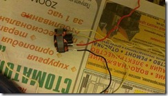
If anyone is interested, I’ll try to tell you more. A computer cooling cooler or similar 12 volt is used as a pulse generator, but with one condition - it must have a built-in hall sensor. It is the hall sensor that will generate pulses for the high-voltage transformer, which, in in this case, an ignition coil from a car is used. Choosing a suitable fan is very simple; as a rule, it has three inputs.

The photo shows the presence of three conclusions. The standard color is red pin plus power, black – common (ground) and yellow – output from the hall sensor. When power is applied to the fan, the output ( yellow wire) we receive pulses, the frequency of which depends on the speed of the electric motor of a given cooler and the higher the voltage, the higher the frequency of the pulses. The voltage should be increased within reasonable limits - approximately 12-15 volts, so as not to burn the cooler and the entire circuit. The resulting pulse signal must be applied to the ignition coil, but it must be amplified.

As a power switch I used an “N” channel field-effect transistor (mosfet) IRFS640A; others with similar parameters are suitable, or approximately for a current of 5-10 amperes and a voltage of 50 volts for reliability. Mosfets are present in almost all modern electronic circuits, be it motherboard computer or the starting circuit of an energy-saving lamp, which means there will be no problems finding a suitable one.

The ignition coil from VAZ “classic” B117-A cars has three terminals. The central one is a high-voltage output, “B+” is positive 12 volts, and the general “K” is probably not marked.
Initially, the circuit consisted of three components: a cooler, a mosfet and a coil, but after a short time of operation it broke down, as either the mosfet or the hall sensor failed. Output – setting 100 Ohm resistors for limiting starting current from the hall sensor to the gate, and a 10 kOhm pull-up resistor to shut off the mosfet in the absence of a pulse.

When assembling the circuit, the transistor should be installed on a radiator, preferably using thermal paste, since the heating during operation is significant.

I used the connector from the cooler as a terminal block to connect the mosfet. As a result, there is no need to solder the transistor; to connect or replace it, just connect the block to the terminals of the transistor.

The fan was secured on top of the radiator using two self-tapping screws. As a result, it turned out that the cooler plays a dual role - as a pulse generator and as additional cooling.
I was prompted to build this wind generator by one of the publications I came across about homemade wind generators. From this article I realized that there is nothing particularly difficult in building a small windmill, the main thing is desire. The idea of providing for yourself autonomous source energy had been in my head for a long time, and after looking at the experiences of others, I decided to build my own windmill.
Such wind generators were often made using small motors DC, from all sorts of scanners, drives, and I decided to repeat these rather successful experiments. In terms of price, such a wind generator will cost no more than 2-5 thousand rubles, the main price is the electric motor, which will be used as a generator. At economical consumption you can generate 50...250 W, which is much cheaper than panels solar panels similar power. Here, for those who are interested, is my story about how I built the generator.
To build such windmills, you don’t need special tools, but rather what almost everyone has in their garage or closet is enough. To make my design, I only needed a drill and a jigsaw, which I used to cut out the blades, and other little things (keys, bolts, ruler, tape measure, pencil, etc.) in general, something that is usually available or purchased in a store for small money.
I myself have a very modest budget, so I decided to make the cheapest wind generator possible, so I looked for the simplest and most affordable ways to build my own wind turbine. For the construction, I made the most of the materials that were available and lying idle on my site.
P y P f There is nothing complicated in making blades. Usually the pipe is divided into three equal parts lengthwise and sawn. This material saws quite well and can even be sawed with a hacksaw, but I had a jigsaw, which made the task easier, although they also often saw with blades for metal.
Next, I had to attach the blades to the shaft of the motor-generator, and I decided to use a metal disk from a circular saw, they drill well, are very durable and light. To secure it to the shaft, I used an adapter, this is a special attachment for attaching disks to the shaft.
Having previously marked the disk, I drilled holes for the bolts for fastening the blades and assembled everything into a single structure, below you see what I got. I think it turned out successful, reliable, simple and neat.
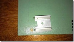
Next, I had to secure the generator to something, and for this I used a piece of a square. I didn’t bother with the fastening, but simply pulled the generator to the beam with clamps, additionally wrapping it in a casing made from a piece of PVC pipe.
 >
>
 >
>
 >
>
The tail was cut out of an aluminum sheet, and for fastening in the beam, I cut two lines along which the tail is inserted and secured to the bolts through drilled holes. As a rotary axis, I used a piece of pipe and a flange, which I screwed to the beam after pre-drilling the holes. Below is a photo of an almost finished wind generator; all that remains is to build a mast and raise it into the wind.
 >
>
 >
>
 >
>
During assembly I painted all the parts at once. car paint in cans. The mast was assembled from water pipes Using ready-made adapters, this made it possible to significantly simplify the assembly process without resorting to welding or drilling for bolts. During the assembly process, I worked like a mechanic using adjustable wrenches, as if assembling a water supply unit. The result is a fairly strong and reliable mast.
In this article I will tell you how to make an engine - a Bedini generator from a computer cooler. This device model is one of the lowest power, but at the same time it is very convenient to use, cheap and easy to manufacture. It is very convenient to conduct experiments with the model. It takes up very little space and is easy to maintain. I will tell you the best, in my opinion, way of making it.
You will need: Transistor 2N3055 TO-3; Diode 1 N 4001 and 1 N 4007; Resistor 47 Ohm - 100 Ohm (I recommend 51 Ohm, 1W -2W); 1kΩ trim resistor (I recommend R-17N1-B1K, L15KC or 3296W-1-102LF potentiometer 1K(SP5-2VB)); computer cooler (I took JF0925S1H, fan 12V, 92x92x25mm), but in general it doesn’t matter what kind of stickers there will be on the cooler; terminals, crocodiles. You can buy all this at a radio store, electrician, or take it out of radio devices; I bought it at the Voltmaster store. I really liked the store, their prices are an order of magnitude lower than others. You also need a neon light bulb NE - 2. Take it out of the starter for the fluorescent lamp, a radiator (you can take a piece of aluminum, you can pull it out of some unnecessary radio equipment), a piece of plywood or organic glass 16.5mm*15.5mm and other small fittings (single-core and stranded wires, bolts, nuts).

Here is the diagram to assemble:

Here is a visual diagram:


Now attach the transistor to the heatsink and the heatsink to the base.


The next step is to prepare the cooler. Remove the sticker, then the rubber plug from reverse side. Using a small screwdriver or tweezers, remove the cotter pin (circlip). Remove the blades.

You will see 4 coils attached to the chip with three legs. Grab the core of the coils with pliers and insert a small screwdriver into the space for the blade axle. Holding everything firmly by the core, hit the screwdriver with a hammer. The microcircuit with coils must separate from the entire structure.

Unsolder the coils from the microcircuit. The chip has 3 pins, you must insert a cutoff pin as the fourth pin. There are 2 wires soldered to one of the legs, unsolder one and solder it to the new leg so that there is one wire going to each leg.

Place the coil assembly back onto the axle, solder 4 different colored wires and lead them out.
