Pantograph for drawing with your own hands. Wood copying and milling machines
Quite often it is necessary to enlarge (or reduce) some drawing, drawing or diagram several times. For example, you liked the burning patterns in the magazine. But in the magazine they are usually given in a reduced form, so you have to enlarge them to the required size yourself, either manually using the “cell method”, or using devices: an epidiascope, or a pantograph (copier).
Pantograph (the name comes from two Greek words (pantos) - everything and qrapho - I write) - a device in the form of a sliding articulated parallelogram for redrawing pictures, drawings, diagrams in a different (increased or reduced scale). The main advantages of this device are the simplicity of the design and the fairly high “accuracy” of the copied image. Unfortunately, the pantograph has not yet found due recognition among amateur artists and other handy admirers of decorative and applied arts.
It is now very difficult to find commercially produced pantographs (copiers) on sale. In addition, the range of such pantographs is relatively small, and they are made of metal, which does not make the device convenient enough. So God himself ordered to make for himself a pantograph (copier) with long wooden rulers.
Pantograph is enough high quality Anyone can make it with their own hands, provided the exact dimensions of all parts are observed.
.
Design homemade pantograph(copier), which we want to bring to your attention, consists of four lever-rulers (three long and one short), in which holes are drilled in a certain order to secure the axes. Brass bushings are inserted into the holes of the rulers.
Pantograph mechanism axes various designs, the two central axes are a pin with a head. The axes for attaching the lead (copier) and the tracking rod are made like a device for clamping the lead in the leg of the compass. It is advisable to use a plastic tip as a tracking rod. This tip does not spoil the original and provides good glide. One axis (extreme) with a heel on which the pantograph mechanism rests, and, finally, an axis that secures the entire mechanism to the base boss.
All axes have an annular groove in the upper part, which serves to secure a wire pin-clamp.
The boss is metal. Three stings (gramophone needles) are embedded into the boss from below, making it easy to fix the base on the drawing board.
Rulers are best made of plastic, for example, plexiglass (plexiglass), 5 mm thick. The most important operation is marking and drilling holes in the rulers, so it must be approached with care. special attention. To ensure high accuracy and alignment of the holes, it is enough to make markings on one ruler, put all the rulers in a bag and drill holes in all the rulers along the marked ruler in one step. Try to make the diameter of the holes such that the bushings fit into them tightly, with a slight interference fit.
The bushings are machined from brass according to the dimensions given in Fig. 2. Axles - steel. The length of the axles is directly dependent on the length of the bushing. Bend wire pins-clamps from steel wire with a diameter of 1.2-1.5 mm.
The base boss can be made from an aluminum block 39 mm thick. In the lower part of the boss, punch three needles into the blind holes (you can use a gramophone), so that their points protrude 2-3 mm.
Specification of parts for a homemade pantograph
| Letter designation details | Part name | Quantity | Dimensions in mm | ||
|---|---|---|---|---|---|
| Length | Width | Thickness | |||
| A | Large ruler | 3 | 406 | 20 | 5 |
| B | Ruler small | 1 | 220 | 20 | 5 |
| IN | Base (boss) | 1 | 60 | 40 | 30 |
| G | Bushing | 12 | 8 | - | Ø8 |
| D | Fixing axis | 1 | - | - | - |
| E | Axle support with heel | 1 | - | - | - |
| AND | Copier axis (original) | 2 | - | - | - |
| Z | Middle axis | 2 | - | - | - |
| AND | Pin clamp | 6 | - | - | 1,2-1,5 |
 When all the parts are ready, assemble the pantograph mechanism. When assembling and adjusting parts, try to ensure ease of movement of all links of the mechanism, for which their rubbing surfaces can be slightly lubricated.
The final step in making a homemade pantograph with your own hands is to mark the holes on a ruler, according to which it will be easy to select the scale of enlargement (reduction) of the copy.
Be sure to check the correspondence of the markings with the resulting dimensions experimentally.
How do they work with a pantograph (copier)?
 First of all, the pole (needle) of the pantograph is attached to a certain point on the table. The drawing from which a copy needs to be made is placed where the spire is located, and blank slate paper - under the pencil. Next, we draw the pin along all the lines of the drawing, while the pencil automatically draws an enlarged drawing on the paper. And if you need to depict the drawing in a reduced form, you will have to use a pin and a pencil in places, which is not at all difficult if you have sleeves.
Usually, when working with a pantograph, the hand of the artist guides the pin along the lines of the pattern. In this case, you will have to attach a weight (nut, lead plate) to the ruler next to the pencil so that the pencil is pressed against the paper. But you can copy in another way. Namely, move your hand not with a pin, but with a pencil, while ensuring that the marker moves correctly along the lines of the pattern. In this case, the weight on the ruler, of course, is not needed.
And a few more practical tips.
If the original from which the copy is made has too much large sizes and it is not possible to go through all its lines with a pin at one time, just move the needle to a new place and continue working.
When you enlarge (or reduce) a drawing or drawing, straight lines and circles usually turn out to be of poor quality. Therefore, you will have to correct such a defect using a ruler and compass.
It is known that fairly good copy accuracy is ensured by enlarging the original no more than 2...3 times. Therefore, if you need to enlarge the drawing 4 times, it is better to first enlarge the original by 2 times, and then enlarge the resulting copy again by 2 times.
It is not forbidden to change the dimensions of the pantograph rulers, making them smaller, for example. In this case, the method for calculating the locations of holes on the rulers remains the same, that is, the length of the working part of the ruler will have to be divided by the magnification factor.
IN modern world Often there is a need to create a copy of something or reproduce and repeat something. For this purpose, many enterprises widely use copy-milling machines, which are intended to create products whose shape most closely matches the given original sample. They make it possible to produce parts in large quantities, while ensuring high speed of processing and manufacturing of each element.
Features of the milling procedure
Milling is one of the common machining methods. Using milling, roughing, finishing and semi-finishing of shaped and simple surfaces of workpieces made of steel, non-ferrous metal, cast iron and plastics is carried out. Milling is characterized high level productivity, which allows the final result to obtain products of the correct geometric shape.
Milling can be carried out in two ways: the procedure of up milling (against the feed), when the feed is opposite to the direction of rotation of the cutter, and down milling (along the feed), when the directions of rotation of the cutter and feed coincide. Using cutters that are equipped with modern cutting materials (mineral ceramics, synthetic super-hard), you can process materials that are hardened to high hardness, thereby replacing the grinding procedure.

Milling machines are intended for milling the surfaces of levers, strips, housings, covers and brackets of simple configurations, complex configurations of contours (such as templates, cams), surfaces of body parts. Milling machines are divided into two main categories: machine tools general purpose and specialized devices. The first group includes longitudinal milling, cantilever, non-cantilever and continuous milling machines. The second category includes thread-milling, gear-milling, slot-milling, key-milling and copy-milling machines.
Purpose of a copy milling machine
Copy milling machines are usually used to perform copying works in volume and on a plane, as well as in volume using volumetric models and corresponding copiers, for engraving various shaped profiles, patterns, ornaments and inscriptions, as well as for light milling work. The indisputable advantage of such units is that it is capable of performing with its own simple device incredibly complex patterns.
The machine can perform various milling operations on steel, cast iron and non-ferrous metals using high-speed and carbide tools in large- and small-scale production. Such machines are used to produce ship propellers, turbojet engine blades and steam turbines, hydraulic turbine impellers, cutting and forging dies, press and casting molds, various cams, stamps, molds, metal models and blanks.

Such equipment is also used for drilling holes for handles, locks, latches, metal hinges, as well as making frames for mirrors and channels of any size on plastic and aluminum profiles, as in the video about copy-milling machines. On universal machines, the processing procedure for such products is almost impossible.
A copy-milling machine is intended for milling curved parts using a copying technique according to a template from which the shape of the future product is copied. The use of templates makes it possible to eliminate the influence of the human factor during such a complex operation, and all finished parts as a result have same shape.
To make several completely identical products, you can not only use a single template, but also make all subsequent parts based on the first one. However, for the most accurate repetition, it is recommended to supplement the machine with a copying device called a pantograph. Its design can be different, but the function is the same in all cases - to more accurately transmit the movement of the copying head along the profile to the cutting device.
Design of copy milling machine
The copy-milling machine is designed for processing profiles (planar milling) or reliefs (volume milling) of products using a carbide cutting tool - a milling cutter. The cutter reproduces on the product the contour or surface of the setting device - the copier. The driving device of a manual copy-milling machine has a pneumatic, mechanical or hydraulic connection with a tracking system, which is responsible for directing the cutting tool, on the one hand acting on the intensifying device, and on the other influencing the executive body.
A flat template, a spatial model, a reference part, a contour drawing can act as a copier, and a probe, a copy roller or finger, or a photocell can serve as a copy device. Copy samples can be made of metal, plastic or wood. The workpiece and the copier are mounted on a rotating table.

The executive body can be a spool, a screw, a solenoid, an electromagnetic clutch, or a differential. In the amplification devices of copy-milling machines, electromagnetic, hydraulic or electro-optical relays are used. The surface roughness of the workpiece and the accuracy of the profile depend on the speed of movement of the tracking device: roughness No. 6 and a profile accuracy of 0.02 millimeters are achieved. The actuator circuit is driven by a power hydraulic cylinder and an electric motor.
Copying at a specified scale is carried out using a special device called a pantograph. If you are interested in how to make a copy-milling machine yourself at home, then you can supplement it with this device. The pantograph has a structural guide pin, which is located on an axis and moves along the copier, a rotation axis and a tool spindle. When moving along the finger pattern on the workpiece, the spindle describes a geometrically similar figure. And the copying scale is determined by the proportions of the pantograph arms.
Types of copy milling machines
Based on the type of drive, the following main types of copy-milling machines are distinguished: with a pantograph, which is designed to work in 2 and 3 dimensions; universal devices with a pantograph, which is located on a rotating arm in a vertical plane; single and multi-spindle units with rectangular and round table; with mechanical feed, electrically and hydraulically, as well as photocopying.

There are several types of similar milling and copying machines, which differ in the level of automation and clamping of the workpiece being processed:
- Manual or desktop copy-milling machine with mechanical profile clamping. With its help, you can carry out the drilling procedure various shapes according to the template, however, for triple holes you will need a three-spindle attachment on a machine or drill.
- Automatic (stationary) milling copying machine with pneumatic profile clamp. Such machines also do not allow triple holes to be made for installing handles and, as a rule, are used for the production of aluminum structures.
- Automatic (stationary) milling and copying machine with pneumatic profile clamping and a 3-spindle attachment for drilling triple holes.
Operating principle of a copy milling machine
Processing of products on a copy-milling machine is carried out using a master device (copier), the action of which causes, through the copy device, a corresponding movement relative to the workpiece of a special cutting tool. Through the copying device, the copier acts on the actuators, while the workpiece and the cutter recreate in relative motion the surface that is specified on the copier.
The main movements are rotation of the spindle, movement of the table and slide along the contour, and movement of the spindle head when cutting. Auxiliary movements - acceleration of movement of the slide, spindle head and table, installation movements on the table of the tracer table, stops, copying finger and clamping of the spindle head.

Copy milling machines for aluminum are capable of operating according to 2 tracking schemes: actions with feedback and simple action. The copy probe and the cutter in the simple-action scheme are rigidly connected to each other, and the movement of the probe along the copier is transmitted to the cutter. The deflection of the trace probe in a feedback circuit causes a mismatch in the position of the trace probe relative to the cutter.
The result of such a mismatch is sent to a special tracking system, which issues a signal to the actuator to adjust the tool path. In this case, there is no rigid connection between the cutter and the copier, and the copier does not perceive the cutting force, but only transmits the corresponding signal to the executive bodies.
There are two types of copy milling - volumetric and contour. When contour copying, the copier curve can be placed in a plane that is parallel or perpendicular to the axis of the cutter. In the first case, the table with a copier and the workpiece moves in the longitudinal direction; control of the change in the curve is accomplished due to the vertical movement of the cut-in and the carbon finger. In the second case, the table with the copier and the workpiece moves in the transverse and longitudinal directions according to the shape of the curved line of the copier.

During volumetric copying, the complex spatial surface of a workpiece is processed with a cutter sequentially, through several parallel table strokes, that is, contour copying is performed with each working stroke. At the end of the pass, the cutter is shifted relative to the workpiece perpendicular to the line by the amount of the transverse feed, then the next working stroke occurs.
There are also copy milling machines direct action, in which the cutter probe transmits movement through the pantograph. Such machines are mainly used for light engraving and milling work. When using a pantograph, in addition to copying, it is possible to reduce the scale of workpieces in relation to the copier. The movement of the copy probe along the copier, which is installed on the machine table, is transmitted to the spindle, which, when processing the workpiece, describes a contour similar geometrically to the copier.
Do-it-yourself copy-milling machine
Currently, the market offers milling and copying machines of the most different designs and level of difficulty. However, it is not always possible to buy one, and the price of a copy-milling machine is quite high. Therefore, we often face the question of how to make a copy-milling machine at home.
Of course, homemade machines cannot fully compete with industrial models, but they are still functional and allow you to make high-quality copies. I would like to immediately make a reservation that the copying device should be adapted to industrial milling device It will be very difficult, and this concerns, first of all, a radical redesign of the entire apparatus. Therefore, the easiest way to assemble a homemade copy-milling machine is practically “from scratch” using a rod system and an electric motor with a clamping chuck for the cutter.
There can be many designs of copy-milling machines. Typical design The apparatus is as follows: the machine structurally consists of a work table, a supporting frame and a milling head. The working surface can be adjusted in height, the milling head is equipped with an electric drive motor and a two-stage transmission mechanism that provides two speeds of the milling shaft.
Many homeowners complain that when copying a product, the resulting part has many flaws and inconsistencies that appeared when changing the direction of the cutter, vibration and trembling supporting structure. Adding to the trouble is the sagging and curvature of the workpiece, which is associated with an increase in internal stress due to the removal of wood. It is impossible to avoid all the shortcomings when making a homemade copy-milling machine. It is simply recommended to make the copying machine narrow-profile, and not universal.

A homemade copy-milling machine should be optimized for the production of specific products that you need. For example, for efficient manufacturing the wooden part of the gun and the propeller screw require different technical solutions, they cannot be combined in one machine, and side effects that are difficult to correct may occur. Thus, it is more practical to assemble machines for some certain tasks. This approach can save you many costs and difficulties.
An important factor is the size of the machine. The larger the product you plan to process, the more massive the design should be. It is necessary that the vibrations transmitted from the cutter drive are absorbed by the weight of the machine's supporting structure. Loads must be supported by guide axes, which must also have a safety margin and not bend. The optimal parameters when designing a copy-milling machine with your own hands are selected experimentally, this ensures smooth operation of the cutter.

When designing a copy-milling machine, determine the type of parts you will produce. To perform engraving work and to mill long products, a different work table and a method for securing workpieces with a template on it are required. Freedom of movement in different planes of the cutting tool depends on the type of work table.
The power of the electric motor, which rotates the cutter and is installed on a homemade copy-milling machine, depends on the parts being manufactured and their material. For engraving and milling wooden products A 150-200 watt DC electric motor is sufficient.
To ensure an accurate copying procedure, you need to rigidly connect the copying probe and the device to each other, securing it in cutting tool. In this case, their height and planes above the desktop must coincide completely. The created rigid structure should be installed above the desktop in such a way that it can move in the vertical and horizontal planes along the axes that are conventionally created by the sides of the desktop.
Quite often it is necessary to enlarge (or reduce) some drawing, drawing or diagram several times. For example, you liked the burning patterns in the magazine. But in the magazine they are usually given in a reduced form, so you have to enlarge them to the required size yourself, either manually using the “cell method” or using instruments: an episcope or a pantograph.
ABOUT self-production the episcope has already been described in the almanac. Now let's look at the pantograph.
Pantograph (the name comes from two Greek words (pantos) - everything and grаho - I write) - a device in the form of a sliding articulated parallelogram for redrawing drawings, drawings, diagrams in another (increased or reduced scale). The main advantages of this device are its simplicity of design and fairly high
what is the “accuracy” of the copied image. Unfortunately, the pantograph has not yet found due recognition among amateur artists and other handy admirers of decorative and applied arts.
It is now very difficult to find commercially produced pantographs on sale. In addition, the pins of such pantographs are relatively small, and they are made of metal, which does not make the device convenient enough. So God himself ordered to make for himself a pantograph with long wooden rulers.
As already mentioned, the pantograph has the form of a sliding parallelogram and consists of four wooden planks (rulers), fastened together using hinges so that the rulers can move and move apart like an accordion (Fig. 1). As can be seen from the figure, at the ends of the pantograph bars there is a needle (pole), a mark (pin) and a pencil. When working, the needle is fixed at some point on the table, the mark is drawn along a given contour, and a pencil draws a copy of this contour, but on a given scale.
First of all, for the pantograph it is necessary to make four rulers 630 mm long, 15 mm wide and 4 mm thick. It is better to cut such pins from thin slats, but they can also be cut from plywood. On all rulers, the working part is first marked, for which 15 mm are set aside from the ends of the pins. Thus, there will be a distance of 600 mm between the marks, which will be the working part of the ruler. We denote the beginning of the working part of the ruler by the letter H, and the end by the letter K. Of course, we choose the beginning and end of the working part arbitrarily.
Next, we will mark on the working part of each ruler the centers of the holes that we will need when adjusting the pantograph to one or another magnification. Let's assume that for our work we need to enlarge the original by 1.25; 1.5; 2; 3; 4; 5; 6 and 7 times. And to get, for example, the center of a hole with a magnification factor of 1.25, you need to divide the length of the working part by 1.25 and put the resulting size on a ruler, taking point H as the starting point. That is, the center of the desired hole will be at a distance of 480 mm from the beginning of the working part. In the same way, from point H we determine the distance of the centers of the holes to increase the original by 1.25; 2; 3 times and so on (Fig. 2). Having marked the position of the centers on the rulers, at each mark we write a number that will correspond to the degree of magnification of the drawing.

Using the resulting markings, we drill holes in the rulers for the bolts that are supposed to connect the rulers. Bolts with M3 or M4 threads are most suitable for these purposes; accordingly, holes for them are needed with a diameter of 3 or 4 mm. But we make the outer holes at points H and K with a diameter of 5.6 mm, that is, the diameter of the shells from a small-caliber rifle, which we will use to attach a needle, a mark and a pencil to them. Next, using pins, we hinge the rulers in pairs, aligning the end of one pin with the beginning of the other (Fig. 3, a), after which we flare the open ends of the sleeves. All that remains is to select the magnification factor and connect the pairs of rulers, installing the bolts in the holes with the required index. Thus, the pantograph shown in Fig. 3, b, ready to enlarge the original by 4 times.

At point P (Fig. 3, b) there is a pantograph pole (needle), at point O (the point where the pair of rulers are hinged) there is a marker, at point P there is a pencil. If the ends of the rulers were connected using sleeves, attaching a needle, a mark and a pencil to the pantograph is very simple. To install the needle, you need to tightly insert a stick (wooden plug) into the appropriate sleeve, and then hammer a piece of a thick needle into the center of which with the blunt end. But you can fix this fragment of a needle in a sleeve by pouring molten tin or lead into it.
A pointed stick is suitable as a marker; it is not at all difficult to secure in the desired sleeve. The end of the stick should protrude from the sleeve by about 1 cm. If a long bolt is used instead of the sleeve, it is oriented with the head up, secured with a nut, and the end is sharpened with a file. Installing a pencil into the sleeve is also not a problem.
We emphasize once again that when making a pantograph, precise marking of the holes is necessary, as well as full compliance of the diameter of the hole in the ruler with the diameter of the bolt. Only then can a pantograph be used to achieve sufficient accuracy even when copying very complex designs.
How do they work with a pantograph? First of all, the pole (needle) of the pantograph is attached to a certain point on the table. The drawing from which you want to make a copy is placed where the pin is located, and a blank sheet of paper is under the pencil. Next, we draw the pin along all the lines of the drawing, while the pencil automatically draws an enlarged drawing on the paper. And if you need to depict the drawing in a reduced form, you will have to use a pin and a pencil in places, which is not at all difficult if you have sleeves.
Usually, when working with a pantograph, the hand of the artist guides the pin along the lines of the pattern. In this case, you will have to attach a weight (nut, lead plate) to the ruler next to the pencil so that the pencil is pressed against the paper. But you can copy in another way. Namely, move your hand not with a pin, but with a pencil, while ensuring that the marker moves correctly along the lines of the pattern. In this case, the weight on the ruler, of course, is not needed. And a few more practical tips.
If the original from which the copy is being made is too large and it is not possible to go through all its lines with a pin at one time, simply move the needle to a new place and continue working.
When you enlarge (or reduce) a drawing or drawing, straight lines and circles usually turn out to be of poor quality. Therefore, you will have to correct such a defect using a ruler and compass.
It is known that fairly good copy accuracy is ensured by enlarging the original no more than 2…3 times. Therefore, if you need to enlarge the drawing 4 times, it is better to first enlarge the original by 2 times, and then enlarge the resulting copy again by 2 times.
It is not forbidden to change the dimensions of the pantograph rulers, making them smaller, for example. In this case, the place for calculating the positions of the holes on the rulers remains the same, that is, the length of the working part of the ruler will have to be divided by the magnification factor.
N. Morozov, Do It Yourself Magazine No. 6-98. Articles
Both in production and at home, there is often a need to produce a part whose shape and dimensions are completely identical to the original sample. At enterprises, this problem is solved using a device such as a copy-milling machine, which allows you to produce copies of the original part in large series, differs high speed, as well as the quality of the processing performed.
What is the milling process?
Copy-milling machines and any other equipment of the milling group can be found on almost any industrial enterprise. This is explained by the fact that the milling operation is one of the most common methods used to perform machining. This technology allows you to perform a wide range of roughing, semi-finishing and finishing operations with simple and shaped workpieces made of ferrous and non-ferrous metals, and to work on wood and plastic. On modern milling equipment Parts of even the most complex shapes are processed with high precision and productivity.
There are two main types of milling: counter (feed and rotation of the tool are in different directions) and down milling (the tool rotates in the same direction as the feed). The cutting part of tools performing milling is made of various materials, which makes it possible not only to successfully work on wood, but also to carry out processing (including grinding) of even the most hard metals and alloys, artificial and natural stone.
Milling equipment is divided into two types: general purpose and specialized, which includes a copy-milling machine.
Capabilities of copy-milling equipment
The copying machine, which belongs to the milling group, is designed for copying and milling work with flat and three-dimensional parts. In addition, such a device can be used to engrave shaped profiles, apply inscriptions and patterns (even of high complexity) to products, and carry out light milling operations on wood and other materials.

Using tools with cutting parts made of various materials, parts made of cast iron are processed on copy milling machines, different varieties steel and non-ferrous metals. Such devices for producing parts in small and large batches successfully produce blades for turbojet engines and steam turbines, propellers for ships, cutting and forging dies, impellers for hydraulic turbines, molds for pressing and casting, compression molds, etc.
A copy-milling machine performs technological operations that are practically inaccessible to universal equipment. The operating principle of such a machine is based on the copying method, for which a special template is used. The use of a template eliminates the human factor when processing even the most complex parts, due to which all finished products have the same shape and geometric dimensions. Conveniently, one template can be used to accurately manufacture a large batch of parts that will be completely identical to each other.
In order to copy the shape and dimensions of the template as accurately as possible, a copier (pantograph for a router) is installed on a copy-milling machine. The purpose of such a device is to accurately transfer all movements from the copy head to the cutting tool.
How does a copy milling machine work?
Copy-milling machines, as mentioned above, are used for planar (processing of profiles) and volumetric (processing of reliefs) milling. They use cutters as a working tool, which, when processing the contour or volumetric surface of a part, repeat the movements of the copier. The connection between the working element and the tracking system in manual machines is ensured by mechanical, pneumatic or hydraulic elements necessary to generate the force transmitted from the copier to the working element of the copy-milling machine.
The template on such machines is a flat contour or spatial model, a standard part or contour drawings, and the element that reads the shape and dimensions of the template is a copying finger or roller, a special probe, or a photocell. To make a template, you can use an aluminum sheet or a sheet of other metal, plastic or wood. The template and the workpiece are located on the rotating work table of the machine.

The working body of copy-milling equipment comes into motion thanks to such structural elements, such as a screw, spool valve, solenoid, differential or magnetic clutch. Relays installed in the amplification devices of copy-milling machines can be electromagnetic, hydraulic or electro-optical.
The quality of the workpiece (surface roughness, accuracy of shape and size) depends on such a parameter as the speed of movement of the tracking device. In this case, the following characteristics of the finished product can be achieved: roughness – No. 6, profile accuracy – 0.02 mm. The main elements of the executive circuit of such equipment are electric motor and hydraulic cylinder.

A pantograph installed on copy-milling equipment ensures copying at a given scale. The pantograph structure consists of a guide pin, its axis, a tool spindle and a separate axis of rotation. The spindle and guide pin are located on the same rail, the ratio of the arms of which determines the copying scale.
Moving along the contour of the template, the finger sets in motion the rack, which rotates freely on an axis. Accordingly, on the other side of the rack, the machine spindle makes identical movements, processing the workpiece. On do-it-yourself copy-milling machines, such a device will also not be superfluous; its presence significantly increases the functionality of the equipment.
Types of copy-milling machines
The equipment of a copy-milling machine may include drives various types. Based on this parameter, the following are distinguished:
- equipment with a pantograph (suitable for processing parts in 2–3 dimensions);
- devices with a copier mounted on a rotary rack moving in a vertical plane;
- single and multi-spindle machines equipped with rotary tables round or rectangular shape;
- machines, the feed on which is ensured by mechanical, electrical, hydraulic devices;
- photocopying equipment.
A homemade copying machine can be any of these types (including copying and grinding machines). You just need to find drawings on the Internet and select components.

According to the degree of automation and the method of fixing the workpiece, the following categories of copy-milling machines are distinguished:
- manual or tabletop, on which the workpiece is fixed mechanically(on these devices you can drill holes of various shapes in accordance with the template);
- automatic equipment of a stationary type, the workpieces on which are fixed using pneumatic clamps (such machines work with aluminum);
- automatic equipment of a stationary type with pneumatic clamps, on which a three-spindle head is installed (on these copy-milling machines, triple holes are simultaneously drilled, which does not allow the production of units of the two previous types).
How does a copy milling machine work?
As noted above, on a copy-milling machine the workpiece is processed using a master device - a copier. All movements of the copier along the contour or surface of the template are transmitted thanks to a special (copying) device to the working head of the machine in which the cutter is fixed. Thus, the cutting tool exactly repeats all the movements made by the copier used to equip the router.

The movements of the elements of a copy-milling machine during the processing of a part are divided into main (rotation and movement of the spindle when cutting the tool into the workpiece material, movement along the contour of the work table and slide) and auxiliary (movement of the spindle head, slide and table in accelerated mode, as well as installation movements made by the tracer table, the copying finger, the stops and the clamp that fixes the spindle head).
In copy milling machines working on aluminum, two tracking schemes can be implemented: simple action and feedback action. When implementing the direct action scheme, the working body of the machine makes movements due to the fact that it is rigidly connected to the copier. The reverse action scheme does not provide for such a connection and movements from the copier to the working element are transmitted not directly, but through a tracking system.
As mentioned above, contour and volumetric milling is performed on copy milling machines. At contour milling the copier movements occur in a plane parallel or perpendicular to the axis of the tool. In the first case, the movement of the equipment working table can only be longitudinal, and the cutter and copying finger move vertically. In the second case, the table moves both longitudinally and transversely. At volumetric milling the part is processed in stages - thanks to several movements of the table and tool performed in parallel planes.
The direct action scheme can also be implemented through a pantograph, which allows you to reduce the size finished products relative to the size of the template used (scale). Most often, such an additional device, which is easy to make yourself, is installed on machines used for engraving and light milling work.

Another variation of a self-made machine
How to make a copy milling machine with your own hands
Many home craftsmen would like to purchase a copy-milling machine to equip their workshop, but the cost of such equipment is quite high. Meanwhile, if you have the desire, and without spending a lot of time, effort and financial resources, you can make such equipment with your own hands.
Naturally, homemade copy-milling equipment cannot be compared with professional ones in terms of power, reliability and functionality, but such machines can also make high-quality copies, work with wood and process workpieces from other materials. Many people try to attach a copying device to an existing one, but this is impractical, since it would require redoing almost the entire machine. As practice shows, it is better to assemble your homemade copy-milling machine from scratch, selecting the appropriate components for this.
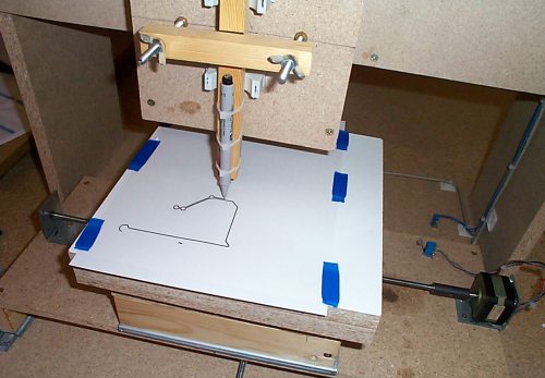
The photo below shows an example homemade machine with a video supplement. The creator of the machine narrates the story in English, but in principle everything is quite clear even without translation.

The easiest way to make a copy-milling device with your own hands is by standard scheme, which includes a supporting structure - frame, desktop and milling head. The drive to ensure the rotation of the working tool is an electric motor that transmits movement through a two-stage mechanism, allowing two speeds to be obtained. Desktop of this homemade device can be adjusted in height.
Many of those who have made a copy-milling machine with their own hands note that when changing operating modes, such equipment begins to show a lot of shortcomings. The most common of these shortcomings are vibrations of the machine frame, curvature of the workpiece and its deflection, poor-quality copying, etc. To avoid such problems, it is best to make the copy-milling device highly specialized and immediately configure it to process workpieces of the same type. This is explained by the fact that it is almost impossible to take into account all the shortcomings that will arise in universal equipment when changing operating modes.
A pantograph is a tool with which you can redraw a plan or map, drawing or drawing, etc. with great accuracy and to the desired scale (Fig. 1).
Such a homemade pantograph is of interest to specialists of many professions - architects, artists, engineers, inventors, innovators.
The pantograph uses the principle of a parallelogram mechanism, which makes it possible for two points of the mechanism to perform absolutely identical movements with one rigidly fixed end. Depending on the size of the selected shoulder, the image scale can be different and change in the desired direction. The scale is fixed and is set according to marks with corresponding digital markings.
How to make a pantograph - a homemade pantograph with your own hands
Anyone can make a pantograph of sufficiently high quality with their own hands, provided that the exact dimensions of all parts are observed (Fig. 2).
The design of a homemade pantograph, which we would like to bring to your attention, consists of four lever-rulers (three long and one short), in which holes are drilled in a certain order to secure the axes. Brass bushings are inserted into the holes of the rulers.
The axes of the pantograph mechanism are of different designs; the two central axes are a pin with a cap. The axes for attaching the lead (copier) and the tracking rod are made like a device for clamping the lead in the leg of the compass. It is advisable to use a plastic tip as a tracking rod. This tip does not spoil the original and provides good glide. One axis (extreme) with a heel on which the pantograph mechanism rests, and, finally, an axis that secures the entire mechanism to the base boss.
All axes have an annular groove in the upper part, which serves to secure a wire pin-clamp.
The boss is metal. Three stings (gramophone needles) are embedded into the boss from below, making it easy to fix the base on the drawing board.
Rulers are best made of plastic, for example, plexiglass (plexiglass), 5 mm thick. The most important operation is marking and drilling holes in the rulers, so it must be treated with special attention. To ensure high accuracy and alignment of the holes, it is enough to make markings on one ruler, put all the rulers in a bag and drill holes in all the rulers along the marked ruler in one step. Try to make the diameter of the holes such that the bushings fit into them tightly, with a slight interference fit.
The bushings are machined from brass according to the dimensions given in Fig. 2. Axles - steel. The length of the axles is directly dependent on the length of the bushing. Bend wire pins-clamps from steel wire with a diameter of 1.2-1.5 mm.
The base boss can be made from an aluminum block 39 mm thick. In the lower part of the boss, punch three needles into the blind holes (you can use a gramophone), so that their points protrude 2-3 mm.
Specification of parts for a homemade pantograph
| Part letter designation | Part name | Quantity | Dimensions in mm | ||
|---|---|---|---|---|---|
| Length | Width | Thickness | |||
| A | Large ruler | 3 | 406 | 20 | 5 |
| B | Ruler small | 1 | 220 | 20 | 5 |
| IN | Base (boss) | 1 | 60 | 40 | 30 |
| G | Bushing | 12 | 8 | - | Ø8 |
| D | Fixing axis | 1 | - | - | - |
| E | Axle support with heel | 1 | - | - | - |
| AND | Copier axis (original) | 2 | - | - | - |
| Z | Middle axis | 2 | - | - | - |
| AND | Pin clamp | 6 | - | - | 1,2-1,5 |
When all the parts are ready, assemble the mechanism. When assembling and adjusting parts, try to ensure ease of movement of all links of the mechanism, for which their rubbing surfaces can be slightly lubricated.
The final step in making a homemade pantograph with your own hands is to mark the holes on a ruler, according to which it will be easy to select the scale of enlargement (reduction) of the copy.
Be sure to check the correspondence of the markings with the resulting dimensions experimentally.