Infrared soldering station with MK control. Let's build! DIY IR soldering station v2 Infrared soldering station
agree.
I don't agree. It’s not the percent who starts to panic, but the programmer who programmed him did not foresee such a situation. What prevents the programmer from taking such a situation into account? Moreover, this function is implemented in the tormentor controller - CUT.
What prevents you from entering the same table into the controller software? For example. The START button is pressed when Tn. = 100 degrees. The controller checks next condition: initial step T = 20 degrees, final step T = 180 degrees, step time is 160 seconds. This means that the increase in T at this step is 1 g/sec. The controller should reduce the heating time by 80 seconds. But I must also take into account (but this condition is not taken into account in the tormentor controller) that if the increase in T at this step should be equal to 1 g/sec, then despite any other factors, namely, time increases or decreases, it must heat no MORE and NO LESS THAN 1g/sec. Moreover, some time is still needed to at least warm up the emitter. Whatever power was set at this step. And the operator shouldn’t really care what power it heats with at the moment station. And the controller should know this from compiled tables, for example, for such a function as auto-tuning. When you turn on the station for the first time, either automatically or via a menu item, the station’s auto-tuning starts. This can be specified in the instructions. Like, first install the board as large as possible, the controller drove up to 100 degrees, which in principle is painless for the board, took measurements, then the middle one, then the smallest one, like MXM. That's all! The controller created a table for itself about which you write “about stoves”. Next, based on this table, the controller does preheating and at the same time DETERMINES what size board is installed. He determines this by the board’s reaction to the rise in T from the power applied to the VI. If he “didn’t like” something, then let him give a signal - it is necessary to carry out auto-tuning. As a result, another board will be added to his table. In terms of time, I don't think this is critical. Because do-it-yourselfers spend significantly more time setting up their home-made products.
ANY soldering controller is just such a device in terms of functionality, even from famous manufacturers. What is a dimer? This is some kind of power control external influence. In the case of a dimer, this is the potentiometer knob. In the case of a soldering iron, a controller. And what you wrote at the end, I wrote at the beginning. There is no time to create a soldering station based on PID and power control. Or rather, it is possible to create it, but it requires very clear and deeply thought-out software.
Continued for Krievs. In the case of multi-stage dimers, this software is an operator who monitors the process and in the event of “something went wrong” makes one decision or another. The only advantage of this solution is its low cost. How correctly I wrote Andy52280, in this case everything goes “to the bulging eye of the sea.”
In continuation I will say that maxlabt I found the most optimal solution for homemade stations. Or rather, he didn’t find it, but he studied the theory as deeply as possible (the nickname helped) and in practice chose the lesser evil of all evils. And the main thing is that he shared his research with everyone. For which I thank him very much. Aries 151 actually costs exactly as much as it can be used, well, maybe a little more expensive. Also, because of its versatility, it is not entirely suitable for our conditions. It is enough to remember how maxlabt I helped one guy on a diamond set up a stove almost online. Damn Hollywood. You open a thread, read the latest messages and wonder, where is the continuation of this fascinating series? So despite all the respect maxlabt for myself I realized that Aries is not IDEAL solution. Optimal - YES, but not ideal. Therefore, I am not ready to spend money on Aries, despite its cost. Although it is not that expensive. If you compare its cost with the prices for repairing laptops, and specifically, when they charge 80 bucks or more for replacing a bridge, not counting the cost of the bridge itself, then the cost of Aries at just over 200 bucks doesn’t seem so much anymore.
It’s better to buy a thermopro then. But this is not my level. I don't need him. It’s much more interesting for me to get candy from what I have at the moment. And what filling this candy will have depends on my knowledge, experience and the degree of curvature of my hands. Good luck to everyone in our difficult task!
Infrared soldering station is a device for soldering microcircuits in a BGA package. If what you read doesn’t tell you anything, you probably shouldn’t go to the cat. There are arduinos, graphs, programming, ammeters, screws and blue electrical tape.
First background.
My professional activity related in some way to electronics. Therefore, relatives and friends are constantly trying to drag me some electronic device that is not quite working properly with the words “well, look, maybe some wiring has come unsoldered.”
At that time, such a thing turned out to be a 17" eMachines G630 laptop. When you press the power button, the indicator came on, the fan made noise, but the display was lifeless, there were no beeps or activity hard drive. An autopsy showed that the laptop was built on an AMD platform, and the northbridge was marked 216-0752001. A quick Google showed that the chip has a very poor reputation for reliability, but problems with it are easily diagnosed. You just need to warm it up. I set the soldering gun to 400 degrees and blew on the chip for 20 seconds. The laptop started up and showed the picture.
The diagnosis has been made. It would seem that it’s a small matter - re-soldering the chip. This is where the first revelation awaited me. After calling service centers, it turned out that the minimum amount for which you can change a chip in Minsk is $80. $40 for the chip and $40 for the labor. For a laptop with a total cost of $150, it was not very budget-friendly. A friendly dating service offered to resolder the chip at cost - for $20. The final price tag dropped to $60. The upper limit of a psychologically acceptable price. The chip was successfully soldered, the laptop was assembled, given away, and I happily forgot about it.
The second background.
A few months after the end of the first backstory, a relative called me and said, “You love all kinds of electronics. Pick up your laptop for spare parts. For free. Or I'll just throw it in the trash. They said it looked like a motherboard. Chip dump. It is not economically feasible to repair.” So I became the owner of a Lenovo G555 laptop without a hard drive, but with everything else, including a power supply. Turning it on showed the same symptoms as in the first prehistory: the cooler is spinning, the lights are on, there are no more signs of life. The autopsy showed an old friend 216-0752001 with traces of manipulation.

After warming up the chip, the laptop started up as if nothing had happened, as in the first case.
Reflections.
So I found myself the owner of a laptop with a faulty north bridge. Should I take it apart for parts or try to repair it? If the latter, then solder it on the side again, even for 60 dollars, and not 80? Or buy your own infrared soldering station? Or maybe assemble it yourself? Do I have enough strength and knowledge?
After some thought, it was decided to try to fix it, and to fix it myself. Even if the attempt is unsuccessful, it won’t hurt to disassemble it for parts. And the infrared station will be a useful aid in many works that require preheating.
Technical specifications.
Having studied the prices for ready-made industrial infrared stations (from $1000 to plus infinity), sifted through a bunch of topics on specialized forums and videos on Youtube, I finally formed the technical specifications:
1. I will make my own soldering station.
2. The design budget is no more than $80 (two solderings at the service center without materials).
Additionally, the following were purchased offline:
Linear halogen lamps R7S J254 1500W - 9 pcs.

Linear halogen lamps R7S J118 500W - 3 pcs.

R7S cartridges - 12 pcs.

The following were pulled out of the trash in the garage:
Docking station from some antediluvian Compaq laptop - 1 pc.

Tripod from a Soviet photo enlarger - 1 pc.

Power and signal wires, an Arduino Nano, and WAGO terminal blocks were found in a home storage room.
Bottom heater.
We arm ourselves with a grinder and cut off everything unnecessary from the docking station.

We attach cartridges to a sheet of metal.

We connect three cartridges in series, resulting in three chains in parallel. We install the lamps and hide them in the housing.

The search for material for the reflector took a long time. I didn't want to use foil because I suspected it wouldn't last long. Use a thicker one sheet metal did not work due to difficulties with its processing. Survey of familiar employees industrial enterprises and bypassing non-ferrous metal purchasing points did not yield any results.
In the end I managed to find sheet aluminum slightly thicker than foil, which was ideal for me.

Now I know exactly where to look for such sheets - from printers. They attach them to the drums in their cars, either to transfer paint, or for something else. If anyone knows, tell me in the comments.
Bottom heater with installed reflector and grille. Instead of a grille, it is more correct to use, but it is not at all budget-friendly, like everything with the “Professional” sticker.

Shines a beautiful orange light. It doesn’t burn your eyes, you can look at the light completely calmly.

Consumes about 2.3 kW.

Upper heater
The design idea is the same. The cartridges are screwed with self-tapping screws to the cover of the computer power supply. A reflector bent from an aluminum sheet is attached to it. Three five hundred watt halogens are connected in series.

It also glows orange.

Consumes about 250 watts.

Control circuit
An infrared station is an automatic machine with two sensors (board thermocouple and chip thermocouple) and two actuators (lower heater relay and upper heater relay).

It was decided that all the heating power control logic would be implemented on a PC. Arduino will only be a bridge between the station and the PC. I received the parameters for PWM control of the heaters from the PC - set them - sent the temperature of the thermocouples to the PC, and so on in a circle.
Arduino expects messages like SETxxx*yyy* on the serial port, where xxx is the power of the upper heater in percent, yyy is the power of the lower heater in percent. If the received message matches the template, the PWM coefficients for the heaters are set and the OKaaabbbcccddd message is returned, where aaa and bbb are the installed power of the upper and lower heaters, ccc and ddd are the temperature received from the upper and lower thermocouples.
A “real” hardware PWM microcontroller with a sampling frequency of several kilohertz is not applicable in our case, since the solid-state relay cannot turn off at an arbitrary point in time, but only when passing AC voltage through 0. It was decided to implement our own PWM algorithm with a frequency of about 5 hertz. At the same time, the lamps do not have time to go out completely, although they flicker noticeably. In this case, the minimum duty cycle, at which there is still a chance to capture one period of the mains voltage, turns out to be 10%, which is quite enough.
When writing the sketch, the task was to refuse to set delays using the delay() function, since there is a suspicion that at the moment of delays, data from the serial port may be lost. The algorithm is as follows: in an endless loop, the presence of data from the serial port and the value of the software PWM time counters are checked. If there is data from the serial port, we process it; if the time counter has reached the PWM switching values, we carry out actions to turn the heaters on and off.
#include
Application for computer.
Written in Object Pascal in the Delphi environment. It displays the state of the heaters, draws a temperature graph and has a built-in primitive modeling language, more reminiscent of some Verilog in philosophy than, for example, Pascal. A “program” consists of a set of “condition - action” pairs. For example, “when the lower thermocouple reaches a temperature of 120 degrees, set the power of the lower heater to 10%, and the upper heater to 80%.” This set of conditions implements the required thermal profile - heating rate, holding temperature, etc.

The app has a timer that ticks once per second. Based on a timer tick, the function sends the current power settings to the controller, receives back the current temperature values, draws them in the parameters window and on the graph, calls the procedure for checking logical states, and then goes to sleep until the next tick.
Assembly and test run.
I assembled the control circuit on a breadboard. Not aesthetically pleasing, but cheap, fast and practical.

The device is finally assembled and ready to launch.

A run on the test board revealed the following observations:
1. The power of the bottom heater is incredible. The temperature graph of a thin laptop board shoots up like a candle. Even at 10% power, the board confidently heats up to the required 140-160 degrees.
2. The power of the upper heater is worse. It is possible to heat the chip even to a temperature of “low +50 degrees” only at 100% power. Either it will have to be redone later, or let it remain as a protection against the temptation to underheat the bottom.
Buying a chip on Aliexpress.
There are two types of bridges 216-0752001 on sale. Some are declared as new and cost from $20 each. Others are listed as "used" and cost $5-$10 each.
There are many opinions among repairmen regarding used chips. From categorically negative (“bugger, come to me, I have a pile of used bridges right under the table after resoldering, I’ll sell them to you inexpensively”) to cautiously neutral (“I plant them sometimes, they seem to work fine, returns, if there are any, are not much more often than new ones").
Since my repairs are ultra-budgetary, it was decided to install a used chip. And to be on the safe side in case of a trembling hand or a faulty copy, a lot “2 pieces for 14 dollars” was found.

Chip removal
We install the board on the bottom heating, attach one thermocouple to the chip, the second to the board away from the chip. To reduce heat loss, cover the board with foil, with the exception of the window for the chip. We place the upper heater above the chip. Since the chip has already been replanted, we load a self-invented profile for lead solder (heating the board to 150 degrees, heating the chip to 190 degrees).
Everything is ready to start.

After the board reached a temperature of 150 degrees, the upper heater automatically turned on. Below, under the board, you can see the heated filament of the lower halogen.

Around 190 degrees the chip “floated”. Since vacuum tweezers did not fit into the budget, we hook it with a thin screwdriver and turn it over.

Temperature chart during dismantling:

The graph clearly shows the moment the upper heater is turned on, the quality of stabilization of the board temperature (large wavy yellow line) and the chip temperature (red small ripples). The red long “tooth” downwards means the thermocouple is falling from the chip after it is turned over.
Soldering a new chip
Due to the responsibility of the process, there was no time to take photographs or take screenshots. In principle, everything is the same: we go over the nickels with a soldering iron, apply flux, install the chip, install thermocouples, work out the soldering profile, and with a slight wobble we make sure that the chip has “floated.”
Chip after installation:

It can be seen that it sat more or less straight, the color has not changed, and the textolite is not bent. The prognosis for life is favorable.
With bated breath we turn on:

Yes! Motherboard started. I re-soldered the first BGA in my life. Moreover, it was successful the first time.
Approximate cost estimate:
Bulb J254: $1.5*9=$13.5
Bulb J118: $1.5*3=$4.5
Cartridge r7s: $1.0*12=$12.0
Thermocouple: $1.5*2=$3.0
MAX6675: $2.5*2=5.0
Relay: $4*2=$8.0
Chips: $7*2=$14.0
Total: $60 minus the remaining spare chip.
The laptop was assembled, and the one found in the table was added to it. hard drive 40 gigabytes, operating system installed. To prevent similar incidents in the future, using k10stat, the supply voltage of the processor core is reduced to 0.9V. Now, during the most severe use, the processor temperature does not rise above 55 degrees.
The laptop was installed in the dining room as a movie library for the youngest member of the family, who refuses to eat without his favorite cartoons.
A soldering iron is good. Good for DIP parts, well, for those for which holes are drilled in boards. No doubt, the soldering iron is also great for SMD components, but for this you need to have a black belt in this discipline. But how, once a year, desolder and then solder a multi-legged SMD chip without special skills and equipment? Well then, read on...
I have always been frightened by multi-legged SMD microcircuits, in terms of installation, and not in appearance, in QFP packages and various SO-shki, I won’t even mention BGA. I once had a bad experience, I did it, and included a controller in the SO housing in the design. During the debugging process something went wrong and I had to resolder it. The board and controller conditionally withstood the first dismantling, but after the second, the board and controller went into the trash. As a result, I installed the chip in a dip package and my torment ended. That's all there is to it, while somehow browsing the Internet, I accidentally ended up in a forum thread forum.easyelectronics.ru, from where I was redirected to radiokot.ru. After visiting Radiokot, I got the idea to make “Prikuyalnik” (® by radiokot.ru). It is the cigarette lighter as a soldering iron that will be the source of infrared radiation.
After rummaging through the bins I found a transformer from an uninterruptible power supply, which I had once been given as a gift. This transformer worked in the conversion mode 12 - 220 V, which means it will work in the opposite direction.
There is a power source! And this is already half the battle. All that was left was to find a cigarette lighter, and it was found at the local market for a symbolic price. Any cigarette lighter will do, be it a Mercedes or a Lada. By the way, the Cossack didn’t have this very important device. I decided to connect the emitter to the transformer via a PWM regulator, which later turned out to be not in vain. I chose a circuit based on the common NE555 chip. According to the experience of other users, it is less capricious.

The NE555 chip, according to the datasheet, is powered by a constant voltage in the range of 4.5 - 16V. You can also consider a slightly more capricious circuit on the UC384x. they are quite common in pulse blocks power supplies, computers are no exception.

I decided not to make a printed circuit board, it was too much honor for three wires. Assembled on a breadboard.

I had to come up with a rectifier. The diode bridge is assembled using Schottky diodes, which were torn out of a burnt computer power supply. Just in case, everything is placed on the radiator, we are not Chinese, we don’t mind. Burnt-out computer power supplies are simply an excellent thing, a source of cases and all sorts of parts with radiators!

Having connected the diode bridge to the transformer and measured the open circuit voltage, I felt a little sad. No, the voltage was sufficient, even too much, 20 V at idle. Too much for my PWM controller. If I had known, I would have made a board based on UC3842, it starts working at 16V and above. But I was sad and okay, I added KREN8A (KR142EN8A, analogue of L7808...) to the power supply, and also hung a cooling fan on it.
As always, I have the minimum, but I want the maximum. I'll probably do the bottom heating too. We'll make do on a budget. The bottom heating will be based on a halogen spotlight; the station is not for constant use. A halogen lamp needs a power regulator, otherwise it will burn everything in the world, checked. I thought about ordering from China thyristor regulator, but time. Buying in the city means overpaying. On occasion I went to a local grocery store, there is a lot of nonsense there. And I noticed a lighting dimer on the counter. Compared to all other electrical installation products, it was distinguished by its inconspicuous appearance and price. The declared power of 600 W pleased me. I bought it for only 35 UAH ($1.3).
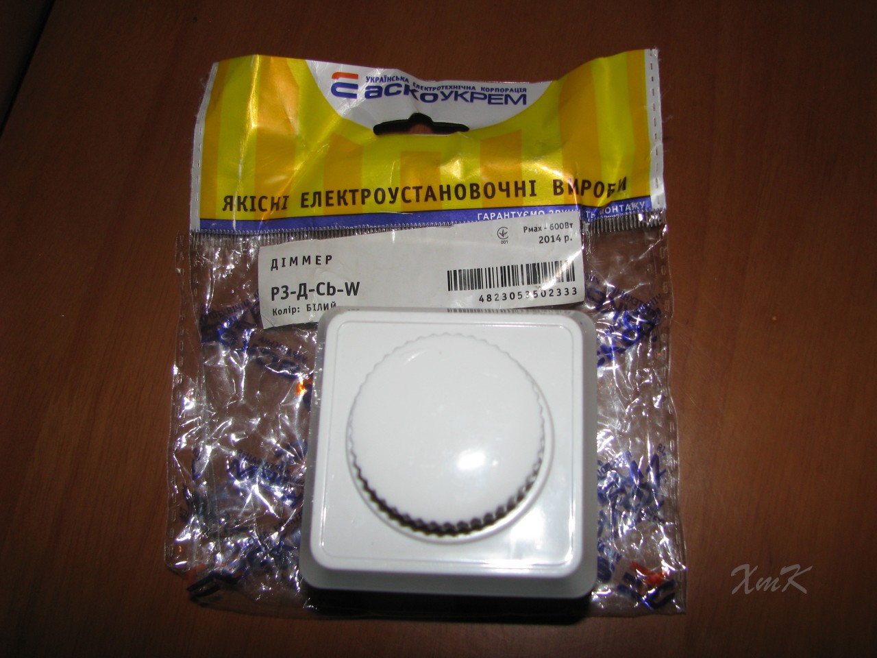
Let's see what's inside. A simple design, assembled on two BT136 thyristors connected in parallel. Excellent redundancy and power reserve. But why with such details and only 600 W?

But now you can see why. I look and think... The potential in our country is huge, but our hands...

I had to wash the board, solder everything again, strengthen the power traces and change the radiator. In the photo below, visible under the orange toggle switch, you can see the new dimer radiator.

A couple of photos of how it was placed in my computer power supply case. Of course there are too many radiators, they are somewhat redundant.

The front panel is made of a piece of polycarbonate (plexiglass). White protective film I didn’t take it off, it gives the feeling that the plexiglass is white and not transparent. And the giblets are not translucent.

And in this photo the top cover is already installed. And here for the first time the hero of the occasion himself appears - the chandelier himself.

The cigarette lighter is screwed to a burnt-out soldering iron. All the insides of the soldering iron have been dismantled.

Fastenings heating element to the base made through annealed steel wire, wound in a spiral to improve heat dissipation. It gets hot and melts the insulation of the wire, so screw it on copper wire It’s not even worth trying directly.

Bottom heating. There are special ones here design features No. A halogen spotlight acts as bottom heating. The spotlight is stabilized by three legs with a rubber base. As you know, a structure on three legs will never swing; it has been proven in geometry that only one plane can be constructed through three points. The glass on top is covered with copper foil with the remains of PCB, once torn off from the old board. A 150 W lamp is installed.

Now the soldering station is ready.

After playing around a bit I can come to some conclusions. You can solder microcircuits with the buoy itself without bottom heating, but it takes a little longer. You can remove small SMDs (resistors, capacitors) using only bottom heating, if you no longer need the board itself. The fact is that there is no thermal stabilization and over time the board begins to overheat; dismantling a large number of elements can take a long time. During experiments, when dismantling on the bottom heating, I overheated the board and it swelled. This swelling was accompanied by a good pop; as they say, I almost “peeed” from surprise. For one-time jobs, you can't imagine anything better.
And in order to show that it still works, I suggest looking at the following photographs.

An old motherboard was chosen as a victim. A chip is selected on it, around which there is large number small components, which makes it difficult to work with a familiar tool. In the next photo the chip is sealed off.
I would like to draw a line under what has been said above. The custodian has the right to be. Of course, it does not claim to be a “professional” tool, but it copes with its tasks. And with today's board architecture, it is simply necessary for an amateur.
Despite the fact that every year more and more new and new technology, more “advanced” in its technical specifications, this does not mean that it will serve forever. Sooner or later, any mechanism fails. And no matter how reliable a part is, this does not insure it against possible failure. And when repairing such equipment, the main tool is a soldering iron. Today we will look at what is special about an infrared soldering station and what it can do.
Design characteristics
A quartz or ceramic emitter can be used as the main heating element in the design of this mechanism. Moreover, both types of devices provide fast and efficient metal soldering. By the way, the heating level of this tool on infrared soldering irons can be varied to varying degrees. Thus, thanks to the presence of a special regulator, you can choose the most suitable temperature regime for the specific type of metal on which the connection (soldering) will be made.
It should be noted that the most popular type of soldering equipment are infrared stations with a type of heating that uses a focused beam. Often the design of such devices consists of two parts, which together provide local heating of the board or other component elements. As a result, you can get very quality connection, while spending a minimum amount of time on soldering.

Varieties
As we noted above, an infrared soldering station can be quartz or ceramic. In order to understand the features of each of them, we will consider both types in more detail.
Ceramic
The ceramic infrared soldering station (including Achi ir6000), due to its simple design, is highly reliable, durable and durable. At the same time, to warm up the entire device to operating temperature Soldering should take no more than 10 minutes. Such stations often use a flat or hollow emitter. The latter type has much greater heating of the working surface of the emitter, as a result of which it quickly performs soldering and heats up to the desired temperature. However, the cost of such devices does not allow them to be used by everyone who repairs electronic digital equipment.

Quartz
The quartz infrared soldering station, despite its increased fragility, has high speed heating In just 30 seconds the emitter heats up to its operating temperature.
An industrial or homemade infrared soldering station is often used for intermittent processes, where there is frequent switching on and off of the device. Ceramic mechanisms are more vulnerable to frequent switching on and can instantly fail if operating rules are not followed.
For a long time now I’ve been thinking about getting a soldering station with my own hands and using it to repair my old video cards, set-top boxes and laptops. An old halogen heating pad can be used for heating, a leg from an old table lamp can be used to hold and move the top heater, the circuit boards will rest on the aluminum rails, a shower coil will hold the thermocouples, and an Arduino board will monitor the temperature.
First, let's figure out what a soldering station is. Modern chips on integrated circuits (CPU, GPU, etc.) do not have legs, but have an array of balls (BGA, Ball grid array). In order to solder/unsolder such a chip, you need to have a device that will heat the entire IC to a temperature of 220 degrees without melting the board or subjecting the IC to thermal shock. This is why we need a temperature controller. Such devices cost in the range of $400-1200. This project should cost approximately $130. You can read about BGA and soldering stations on Wikipedia, and we will start working!
Materials:
- Four-lamp halogen heater ~1800w (as bottom heating)
- 450w ceramic IR (top heater)
- Aluminum curtain slats
- Spiral cable for shower
- Strong thick wire
- Table lamp leg
- Arduino ATmega2560 board
- 2 SSR 25-DA2x Adafruit MAX31855K boards (or do it yourself like I did)
- 2 thermocouples type K
- power unit DC 220 at 5v, 0.5A
- Letter module LCD 2004
- 5v tweeter
Step 1: Bottom Heater: Reflector, Bulbs, Housing


Show 3 more images


Find the halogen heater, open it and take out the reflector and 4 lamps. Be careful not to break the lamps. Here you can use your imagination and create your own housing that will hold the lamps and reflector. For example, you can take old building PC and place the lamps, reflector and wires inside it. I used 1mm thick metal sheets and made housings for the lower and upper heaters, as well as a housing for the Arduino controller. Like I said before, you can be creative and come up with something of your own for the case.
The heater I used was 1800W (4 lamps at 450W in parallel). Use the wires from the heater and connect the lamps in parallel. You can build in a plug for AC, as I did, or connect the cable directly from the lower heater to the controller.
Step 2: Bottom Heater: Board Mounting System


Show 4 more images


After creating the bottom heater body, measure the longer length of the bottom heater window and cut two pieces of aluminum slats the same length. You will also need to cut 6 more pieces, each half the size of the smaller side of the heater window. Drill holes along the two ends of the large pieces of slats, as well as one end of each of the 6 small slats and the long part of the window. Before screwing the parts to the body, you need to create a fastening mechanism with nuts, similar to the one I made in the photographs. This is necessary so that the smaller slats can slide over the larger slats.
Once you've threaded the nuts through the rails and screwed everything together, use a screwdriver to move and tighten the screws so that the mounting system fits the size and shape of your board.
Step 3: Bottom Heater: Thermocouple Holders


To make thermocouple holders, measure the diagonal of the bottom heater window and cut two pieces of spiral shower cable to the same length. Unwind the rigid wire and cut two pieces, each 6 cm longer than the coiled shower cable. Pass the hard wire and thermocouple through the coiled cable and bend both ends of the wire as I did in the pictures. Leave one end longer than the other in order to tighten it with one of the rack screws.
Step 4: Top heater: ceramic plate


To make the top heater, I used a 450W ceramic infrared heater. You can find these on Aliexpress. The trick is to create a good case for the heater with the correct air flow. Next we move on to the heater holder.
Step 5: Top Heater: Holder


Find the old one table lamp on the leg and disassemble it. In order to cut the lamp correctly, you need to calculate everything exactly, since the upper infrared heater must reach all corners of the lower heater. So, first attach the top heater body, make a cut along the X axis, make correct calculations and finally make a cut along the Z axis.
Step 6: PID controller on Arduino


Show 3 more images


Find the right materials and create a durable and safe case for your Arduino and other accessories.
You can simply cut and attach the wires connecting the controller (top/bottom power supply, power controller, thermocouples) using a soldering iron or get connectors and do everything carefully. I didn't know exactly how much heat the SSR would produce, so I added a fan to the case. Whether you install a fan or not, you definitely need to apply thermal paste to the SSR. The code is simple and makes it clear how to connect the buttons, SSR, screen and thermocouples, so connecting everything together will be easy. How to operate the device: There is no auto-tuning for the P, I and D values, so these values will need to be entered manually depending on your settings. There are 4 profiles, in each of them you can set the number of steps, Ramp (C/s), dwel (waiting time between steps), lower heater threshold, target temperature for each step and P,I,D values for upper and lower heaters. If, for example, you set 3 steps, 80, 180 and 230 degrees with a lower heater threshold of 180, then your board will be heated from below only to 180 degrees, then the temperature from below will remain at 180 degrees, and the upper heater will heat up to 230 degrees. The code still needs a lot of improvements, but it gives you an idea of how things should work. This guide does not go into great detail as there are a lot of DIY elements involved and each build will be different. I hope that you will be inspired by this instruction and use it to make your own IR soldering station.