DIY AC voltage stabilizer. Network voltage stabilizer circuit
Household appliances are susceptible to voltage surges: they wear out faster and fail. And in the network, the voltage often jumps, falls, or even breaks off: this is due to the distance from the source and the imperfection of power lines.
To power devices with current with stable characteristics, voltage stabilizers are used in apartments. Regardless of the parameters of the current introduced into the device at its output, it will have almost unchanged parameters.
A current equalizing device can be purchased, choosing from a wide range (differences in power, principle of operation, control and output voltage parameter). But our article is devoted to how to make a voltage stabilizer with your own hands. Is homemade work justified in this case?
A homemade stabilizer has three advantages:
- Cheapness. All parts are purchased separately, and this is cost-effective compared to the same parts, but already assembled into a single device - a current equalizer;
- Possibility of DIY repair. If one of the elements of the purchased stabilizer fails, you are unlikely to be able to replace it, even if you understand electrical engineering. You simply won’t find anything to replace a worn-out part with. With a homemade device, everything is simpler: you initially bought all the elements in the store. All that remains is to go there again and buy what is broken;
- Easy repair. If you have assembled a voltage converter yourself, then you know it 100%. And understanding the device and operation will help you quickly identify the cause of stabilizer failure. Once you figure it out, you can easily repair your homemade unit.
A self-produced stabilizer has three serious disadvantages:
- Low reliability. At specialized enterprises, devices are more reliable, since their development is based on the readings of high-precision instrumentation, which cannot be found in everyday life;
- Wide output voltage range. If industrial stabilizers can produce a relatively constant voltage (for example, 215-220V), then home-made analogues can have a range 2-5 times larger, which can be critical for equipment that is hypersensitive to changes in current;
- Complex setup. If you buy a stabilizer, then the setup stage is bypassed; all you have to do is connect the device and control its operation. If you are the creator of the current equalizer, then you should configure it too. This is difficult, even if you have made the simplest voltage stabilizer yourself.
Homemade current equalizer: characteristics
The stabilizer is characterized by two parameters:
- Permissible range of input voltage (Uin);
- Permissible range of output voltage (Uout).
This article discusses the triac current converter because it is highly efficient. For it, Uin is 130-270V, and Uout is 205-230V. If a large input voltage range is an advantage, then for the output it is a disadvantage.
However, for household appliances this range remains acceptable. This is easy to check, because the permissible voltage fluctuations are surges and dips of no more than 10%. And this is 22.2 Volts up or down. This means that it is permissible to change the voltage from 197.8 to 242.2 Volts. Compared to this range, the current on our triac stabilizer is even smoother.
The device is suitable for connecting to a line with a load of no more than 6 kW. It switches in 0.01 seconds.
Design of a current stabilizing device

A homemade 220V voltage stabilizer, the diagram of which is presented above, includes the following elements:
- power unit. It uses storage devices C2 and C5, voltage transformer T1, as well as a comparator (comparing device) DA1 and LED VD1;
- Knot, delaying the start of the load. To assemble it you will need resistances from R1 to R5, transistors from VT1 to VT3, as well as storage C1;
- Rectifier, measuring the value of voltage surges and dips. Its design includes a VD2 LED with a zener diode of the same name, a C2 drive, a resistor R14 and R13;
- Comparator. It will require resistances from R15 to R39 and comparing devices DA2 with DA3;
- Logic type controller. It requires DD chips from 1 to 5;
- Amplifiers. They will require resistances to limit the current R40-R48, as well as transistors from VT4 to VT12;
- LEDs, playing the role of an indicator - HL from 1 to 9;
- Optocoupler switches(7) with triacs VS from 1 to 7, resistors R from 6 to 12 and optocoupler triacs U from 1 to 7;
- Auto switch with fuse QF1;
- Autotransformer T2.
How will this device work?
After connecting the drive of the node with the pending load (C1) to the network, it is still discharged. Transistor VT1 turns on, and 2 and 3 close. Through the latter, current will subsequently flow to the LEDs and optocoupler triacs. But while the transistor is closed, the diodes do not give a signal, and the triacs are still closed: there is no load. But the current is already flowing through the first resistor to the storage device, which begins to accumulate energy.
The process described above takes 3 seconds, after which the Schmitt trigger, based on transistors VT 1 and 2, is triggered, after which transistor 3 is turned on. Now the load can be considered open.
The output voltage from the third winding of the transformer on the power supply is equalized by the second diode and capacitor. Then the current is directed to R13, passes through R14. At the moment, the voltage is proportional to the voltage in the network. Then the current is supplied to non-inverting comparators. Immediately, the inverting comparing devices receive an already equalized current, which is supplied to resistances from 15 to 23. Then a controller is connected to process the input signals on the comparison devices.
Nuances of stabilization depending on the voltage supplied to the input
If a voltage of up to 130 Volts is introduced, then a low voltage logical level (LU) is indicated at the comparator terminals. The fourth transistor is open, and LED 1 blinks and indicates that there is a strong dip in the line. You must understand that the stabilizer is not able to produce the required voltage. Therefore, all triacs are closed and there is no load.
If the voltage at the input is 130-150 Volts, then a high LU is observed on signals 1 and A, but for other signals it is still low. The fifth transistor turns on, the second diode lights up. Optocoupler triac U1.2 and triac VS2 open. The load will go along the latter and reach the winding terminal of the second autotransformer from above.
With an input voltage of 150-170 Volts, a high LU is observed on signals 1, 2 and V, on the rest it is still low. Then the sixth transistor turns on and the third diode turns on, VS2 turns on and the current is supplied to the second (if counted from above) winding terminal of the second autotransformer.
The operation of the stabilizer is described similarly in the voltage ranges 170-190V, 190-210V, 210-230V, 230-250V.
PCB manufacturing
For a triac current converter, you need a printed circuit board on which all the elements will be placed. Its size: 11.5 by 9 cm. To make it you will need fiberglass, covered with foil on one side.
The board can be printed on a laser printer, after which an iron will be used. It is convenient to make a board yourself using the Sprint Loyout program. A diagram of the placement of elements on it is shown below.

How to make transformers T1 and T2?
The first transformer T1 with a power of 3 kW is manufactured using a magnetic core with a cross-sectional area (CSA) of 187 sq. mm. And three wires PEV-2:
- For the first wrapping, the PPS is only 0.003 square meters. mm. Number of turns – 8669;
- For the second and third windings, the PPS is only 0.027 sq. mm. The number of turns is 522 on each.
If you don’t want to wind the wire, then you can purchase two TPK-2-2×12V transformers and connect them in series, as in the figure below.

To make an autotransformer with a second power of 6 kW, you will need a toroidal magnetic core and PEV-2 wire, from which a wrap of 455 turns will be made. And here we need bends (7 pieces):
- Wrapping 1-3 bends from wire with PPS 7 sq. mm;
- Wrapping 4-7 bends from wire with PPS 254 sq. mm.
What to buy?
Buy in an electrical and radio equipment store (designation in brackets in the diagram):
- 7 optocoupler triacs MOC3041 or 3061 (U from 1 to 7);
- 7 simple triacs BTA41-800B (VS from 1 to 7);
- 2 LEDs DF005M or KTs407A (VD 1 and 2);
- 3 resistors SP5-2, 5-3 possible (R 13, 14, 25);
- Current equalizing element KR1158EN6A or B (DA1);
- 2 comparing devices LM339N or K1401CA1 (DA 1 and 2);
- Switch with fuse;
- 4 film or ceramic capacitors (C 4, 6, 7, 8);
- 4 oxide capacitors (C 1, 2, 3, 5);
- 7 resistances to limit the current, at their terminals it should be equal to 16 mA (R from 41 to 47);
- 30 resistances (any) with a tolerance of 5%;
- 7 resistances C2-23 with a tolerance of 1% (R from 16 to 22).
Assembly features of the device for voltage equalization
The current stabilizing device microcircuit is installed on a heat sink, for which an aluminum plate is suitable. Its area should not be less than 15 square meters. cm.
A heat sink with a cooling surface is also necessary for triacs. For all 7 elements, one heat sink with an area of at least 16 square meters is sufficient. dm.
In order for the AC voltage converter we manufacture to work, you will need a microcontroller. The KR1554LP5 microcircuit copes with its role perfectly.
You already know that you can find 9 flashing diodes in the circuit. All of them are located on it so that they fit into the holes that are on the front panel of the device. And if the stabilizer body does not allow their location, as in the diagram, then you can modify it so that the LEDs come out on the side that is convenient for you.
Instead of flashing LEDs, non-blinking LEDs can be used. But in this case, you need to take diodes with a bright red glow. Elements of the following brands are suitable: AL307KM and L1543SRC-E.
Now you know how to make a 220 volt voltage stabilizer. And if you have already had to do something similar before, then this work will not be difficult for you. As a result, you can save several thousand rubles on the purchase of an industrial stabilizer.
The article discusses the possibility of continuous switching of alternating current circuits using electromechanical relays. The possibility of reducing erosion of relay contacts and, as a result, increasing durability and reducing interference from operation has been shown using the example of a network voltage stabilizer for an apartment.
Idea
I came across an advertisement on the Internet on the website of Pribor LLC, Chelyabinsk:Selenium brand voltage stabilizers produced by our company are based on the principle of step-by-step voltage regulation by continuously switching the autotransformer windings (patent for invention No. 2356082). Powerful, high-speed relays are used as keys.
Pictures of switching are shown (on the left is "Selenium", on the right - with the usual characteristics)


I was interested in this information, I remembered that in the cinema "Ukraine" there was also continuous voltage switching - there, during the switching period, a wirewound resistor was connected between adjacent contacts of the switch. I started looking on the Internet for anything useful about this. I was not able to familiarize myself with invention No. 2356082.
I managed to find an article “Types of voltage stabilizers”, which talked about the possibility of connecting a diode to the relay contacts at the moment of switching. The idea is to switch the AC voltage during the positive half-cycle. In this case, you can connect a diode in parallel with the relay contacts for the switching time.
What does this method provide? Switching 220V changes to switching only 20V, and since there is no interruption of the load current, there is practically no arc. In addition, at low voltages, the arc practically does not occur. There is no arc - the contacts do not burn or wear out, reliability increases by 10 times or more. The durability of the contacts will be determined only by mechanical wear, which amounts to 10 million switching operations.
Based on this article, the most common relays were taken and the switch-off time, the time spent in the broken state and the switch-on time were measured. During the measurements, I saw contact bounce on the oscilloscope, which caused a lot of sparking and erosion of the contacts, which sharply reduces the service life of the relay.
To implement and test this idea, a 2 kW AC relay stabilizer was assembled to power the apartment. Auxiliary relays connect the diode only for the duration of the main relay switching during the positive half-cycle. It turned out that the relays have significant delay and bounce times, but nevertheless, the switching operation was able to be squeezed into one half-cycle.
Schematic diagram

![]()
It consists of an autotransformer switched both at the input and output using a relay.
The circuit uses direct measurement of alternating voltage by a microcontroller. Output voltage via divider R13, R14, R15, R16 is supplied to the input of the microcontroller through a capacitor C10.
The relay and microcircuit are powered through a diode D3 and microcircuit U1. Button SB1 together with a resistor R1 serve to calibrate the stabilizer. Transistors Q1-Q4– amplifiers for relays.
Relays P1 and P2 are the main ones, and relays P1a and P2a, together with diodes D1 and D5, close the circuit when switching the main relays. To reduce the relay switch-off time in relay amplifiers, transistors are used BF422 and the relay windings are shunted by diodes 1N4007 and 150 Volt Zener diodes connected back to back.
To reduce impulse noise coming from the network, capacitors C1 and C11 are installed at the input and output of the stabilizer.
A three-color LED indicates the voltage levels at the stabilizer input: red – low, green – normal, blue – high.
Program
The program is written in SI language (mikroC PRO for PIC), divided into blocks and provided with comments. The program uses direct measurement of alternating voltage by a microcontroller, which simplifies the circuit. Microprocessor applied PIC16F676.Program block zero waits for a falling zero crossing to appear
Based on this difference, either the alternating voltage value is measured, or the relay switches.
Program block izm_U measures the amplitudes of negative and positive half-cycles
In the main program, the measurement results are processed and, if necessary, a command is given to switch the relay.
For each relay group, separate turn-on and turn-off programs are written, taking into account the necessary delays R2on, R2off, R1on And R1off.
The 5th bit of port C is used in the program to send a clock pulse to the oscilloscope so that the results of the experiment can be viewed.
Specifications
When the input voltage changes within 195-245 Volts, the output voltage is maintained with an accuracy of 7%. When the input voltage changes within 185-255 Volts, the output voltage is maintained with an accuracy of 10%Output current in continuous mode 9 A.
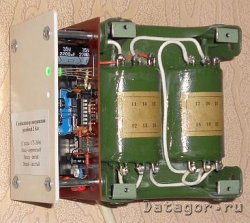
Details and design
A transformer was used during assembly TPP 320-220-50 200 W. Its windings are connected at 240 Volts, which made it possible to reduce the no-load current. Main relays TIANBO HJQ-15F-1, and auxiliary LIMING JZC - 22F.All parts are installed on a printed circuit board mounted on the transformer. Diodes D1 and D5 must withstand a current of 30-50A during the switching time (5-10 ms).

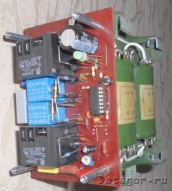
The device is hung on the wall and covered with a tin casing

Settings
Setting up the device consists of checking continuous switching and setting the rated voltage to 220 Volts using the construction resistor R15 and the SB1 button.It is necessary to apply voltage from LATR to the input through an incandescent lamp with a power of 100 - 150 W, set the voltage to 220 Volts and hold the button to achieve a green glow, rotating the construction resistor.
After this, release the button, connect a voltmeter to the output of the device and, rotating the LATR, check the switching thresholds: lower 207 Volts and upper 232 Volts. In this case, the incandescent lamp should not flash or glow during switching, which indicates correct operation. Also, the operation of continuous switching can be seen on an oscilloscope; to do this, you need to connect an external trigger to the RC5 port and observe the output voltage of the stabilizer by changing the input voltage. During switching moments, the sine wave at the output should not be interrupted.
When the output voltage is less than 187V, the red diode lights up and the green diode blinks.
When the output voltage is greater than 242V, the blue diode lights up and the green diode blinks.
The stabilizer has been working for me for the 3rd month and has shown itself to be very good. Before this, a stabilizer of a previous design worked for me. It worked well, but sometimes the computer's uninterruptible power supply would trip when it switched. With the new stabilizer, this problem disappeared forever.
Considering that the erosion of contacts in the relay has sharply decreased (there is practically no sparking), it would be possible to use less powerful relays as the main ones (LIMING JZC - 22F).
Noticed shortcomings
It was quite difficult to select the relay delay time in the program.For such switching, it is advisable to use faster-acting relays.
Conclusions
a) Continuous switching of alternating current circuits using relays is a very real and solvable problem.b) You can use a thyristor or triac as an auxiliary relay, then there will be no voltage drop across the relay, and the triac will not have time to heat up in 10 ms.
c) In this mode, contact sparking is sharply reduced, durability increases, and interference from relay switching is reduced
Sources used
1. on the website “Energy Saving in Ukraine”2. Official website of the enterprise LLC "Pribor", Chelyabinsk
3. Datasheets for details
Files
Schematic, printed circuit board drawing and program with firmware▼ 🕗 12/08/12 ⚖️ 211.09 Kb ⇣ 165 Hello, reader! My name is Igor, I'm 45, I'm a Siberian and an avid amateur electronics engineer. I came up with, created and have been maintaining this wonderful site since 2006.
For more than 10 years, our magazine has existed only at my expense.
Good! The freebie is over. If you want files and useful articles, help me!
After researching sources and a number of sites on the Internet, I simplified the AC voltage stabilizer described in the article. The number of microcircuits was reduced to four, the number of optosimistor switches to six. The principle of operation of the stabilizer is the same as that of the prototype.
Main technical characteristics of the voltage stabilizer:
- Input voltage, V…..135…270
- Output voltage, V. . . .197…242
- Maximum load power, kW………………5
- Load switching or disconnection time, ms…….10
The diagram of the proposed stabilizer is shown in the figure. The device consists of a power module and a control unit. The power module contains a powerful autotransformer T2 and six AC switches, outlined in the diagram with a dash-dotted line.
The remaining parts form the control unit. It contains seven threshold devices: I - DA2.1 R5 R11 R17, II -DA2.2 R6 R12 R18, III - DA2.3 R7 R13 R19, IV - DA2.4 R8 R14 R20, V - DA3.1 R9 R15 R21 , VI - DA3.2 R10 R16 R22, VII -DA3.3 R23. At one of the outputs of the DD2 decoder there is a high level voltage, which causes the corresponding LED to turn on (one of HL1 - HL8).
The powerful autotransformer T2 is connected differently than in the prototype. The mains voltage is supplied to one of the winding taps or to the entire winding through one of the triacs VS1-VS6, and the load is connected to the same tap. With this connection, less wire is consumed on the winding of the autotransformer.
The voltage of winding II of transformer T1 is rectified by diodes VD1, VD2 and smoothed by capacitor C1. The rectified voltage is proportional to the input voltage. It is used both to power the control unit and to measure the input network voltage. For this purpose, it is fed to the divider R1-R3. From the engine of the trimming resistor R2 it goes to the non-inverting inputs of operational amplifiers DA2.1 - DA2.4, DA3.1 - DA3.3. These op amps are used as voltage comparators. Resistors R17-R23 create hysteresis for switching comparators.
The table below shows the limits of change in the output voltage Uout and the logical voltage levels at the outputs of operational amplifiers and the inputs of the DD2 decoder, as well as the turned on LEDs depending on the input voltage Uin without taking into account hysteresis.

The DA1 microcircuit produces a stable voltage of 12 V to power the remaining microcircuits. Zener diode VD3 produces a reference voltage of 9 V. It is supplied to the inverting input of op-amp DA3.3. It is supplied to the inverting inputs of other op-amps through dividers on resistors R5-R16.
When the mains voltage is below 135 V, the voltage on the motor of resistor R2, and therefore on the non-inverting inputs of the op-amp, is less than on the inverting ones. Therefore, the outputs of all op-amps are low. All outputs of the DD1 chip are also low. In this case, a high level appears at output O (pin 3) of decoder DD2. The HL1 LED is on, indicating that the mains voltage is too low. All optosimistors and triacs are closed. No voltage is supplied to the load.
When the network voltage is from 135 to 155 V, the voltage on the motor of resistor R2 is greater than on the inverting input of DA2.1, so its output level is high. The output of element DD1.1 is also high. In this case, a high level appears at output 1 (pin 14) of the DD2 decoder (see table). LED HL1 goes out. The HL2 LED turns on, current flows through the emitting diode of the optocoupler U6, as a result of which the optosimistor of this optocoupler opens. Through an open triac VS6, the network voltage is supplied to the lower tap in the circuit (pin 6) relative to the beginning of the winding (pin 7) of autotransformer T2. The load voltage is 64...71 V higher than the mains voltage.
With a further increase in the network voltage, it will switch to the next output of autotransformer T2 up in the circuit. In particular, the mains voltage from 205 to 235 V is directly supplied to the load through the open triac VS2, as well as to terminals 1-7 of the T2 autotransformer.
When the network voltage is from 235 to 270 V, the outputs of all op-amps, except DA3.3, are high, the current flows through the HL7 LED and the emitting diode U1.2. The network voltage is connected through an open triac VS1 to the entire winding of autotransformer T2. The load voltage is 24…28 V less than the mains voltage.
When the mains voltage is more than 270 V, the outputs of all op-amps are at a high level, and the current flows through the HL8 LED, which signals an excessively high mains voltage. All optosimistors and triacs are closed. No voltage is supplied to the load.
The low-power transformer T1 is similar to that used in the prototype, except that its secondary winding contains 1400 turns tapped from the middle. Powerful autotransformer T2 - ready from the industrial stabilizer VOTO 5000 W. Having unwinded the secondary winding and part of the primary, I made new taps, counting from the beginning of the winding (pin 7): pin 6 from the 215th turn (150 V), pin 5 from the 236th turn (165 V), pin 4 from the 257th turn (180 V), pin 3 from the 286th turn (200 V), pin 2 from the 314th turn (220 V). The entire winding (pins 1-7) has 350 turns (245 V).
Fixed resistors - C2-23 and OMLT, trimming resistor R2 - C5-2VB. Capacitors C1 - SZ - K50-35, K50-20. Diodes (VD1, VD2) can be replaced with -, KD243B - KD243Zh.
The microcircuit can be replaced with domestic analogues KR1157EN12A, KR1157EN12B.
The adjustment is performed using LATR. First, switching thresholds are set. To achieve higher installation accuracy, resistors R17-R23, which create hysteresis, are not installed. The powerful autotransformer T2 is not connected. The device is connected to the network via LATR. At the output of the LATR, the voltage is set to 270 V. The slider of the trimming resistor R2 is moved from bottom to top according to the circuit until the HL8 LED turns on. Next, the voltage at the LATR output is set to 135 V. Resistor R5 is selected so that the voltage at the inverting input (pin 2) of the DA2.1 op-amp is equal to the voltage at its non-inverting input (pin 3). Then resistors R6...R10 are sequentially selected, setting switching thresholds of 155 V, 170 V, 185 V, 205 V, 235 V, checking the logical levels with the table. After this, resistors R17-R23 are installed. If necessary, select their resistances by setting the required width of the hysteresis loop. The greater the resistance, the smaller the loop width. Having set the switching thresholds, connect a powerful autotransformer T2, and to it a load, for example, an incandescent lamp with a power of 100...200 W. Check the switching thresholds and measure the voltage across the load. After adjustment, LEDs HL2-HL7 can be removed by replacing them with jumpers.
LITERATURE:
1. Godin A. AC voltage stabilizer. - Radio, 2005, No. 8.
2. Ozolin M. Improved control unit for alternating voltage stabilizer. - Radio, 2006, No. 7.
Devices for stabilizing network voltage have been used for decades. Many models have not been used for a long time, while others have not yet found widespread use, despite their high characteristics. The voltage regulator circuit is not anything too complicated. The operating principle and basic parameters of various stabilizers should be known to those who have not yet made their choice.
Types of voltage stabilizers
The following types of stabilizers are currently used:
- Ferroresonant;
- Servo-driven;
- Relay;
- Electronic;
- Double conversion.
Ferroresonant stabilizers Structurally they are the simplest devices. They consist of two chokes and a capacitor and operate on the principle of magnetic resonance. Stabilizers of this type are characterized by high response speed, a very long service life and can operate over a wide range of input voltages. Currently, they can be found in medical institutions. They are practically not used in everyday life.
Operating principle of servo drive or electromechanical stabilizer is based on changing the voltage value using an autotransformer. The device is characterized by exceptionally high voltage setting accuracy. At the same time, the stabilization speed is the lowest. The electromechanical stabilizer can work with very heavy loads.
 Relay stabilizer
It also has a transformer with a sectioned winding in its design. Voltage equalization is carried out using a group of relays that are triggered by commands from the voltage control board. The device has a relatively high stabilization speed, but the installation accuracy is noticeably lower due to discrete switching of the windings.
Relay stabilizer
It also has a transformer with a sectioned winding in its design. Voltage equalization is carried out using a group of relays that are triggered by commands from the voltage control board. The device has a relatively high stabilization speed, but the installation accuracy is noticeably lower due to discrete switching of the windings.
Electronic stabilizer works on the same principle, only the winding sections of the control transformer are switched not using relays, but by power switches on semiconductor devices. The accuracy of the electronic and relay stabilizers is approximately the same, but the speed of the electronic device is noticeably higher.
Double conversion stabilizers , unlike other models, do not have a power transformer in their design. Voltage correction is carried out electronically. Devices of this type are characterized by high speed and accuracy, but their cost is much higher than other models. A do-it-yourself 220-volt voltage stabilizer, despite its apparent complexity, can be implemented precisely on the inverter principle.
Electromechanical stabilizer
The servo drive stabilizer consists of the following components:
- Input filter;
- Voltage measurement board;
- Autotransformer;
- Servo motor;
- Graphite sliding contact;
- Indication board.

The operation is based on the principle of voltage regulation by changing the transformation ratio. This change is carried out by moving the graphite contact along the insulation-free winding of the transformer. The contact is moved by a servomotor.
 The mains voltage is supplied to a filter consisting of capacitors and ferrite chokes. Its task is to clean the incoming voltage as much as possible from high-frequency and impulse noise. The voltage measurement board has a certain tolerance. If the network voltage fits into it, then it immediately goes to the load.

If the voltage deviates beyond the permissible limit, the voltage measurement board sends a command to the servomotor control unit, which moves the contact in the direction of increasing or decreasing the voltage. As soon as the voltage returns to normal, the servomotor stops. If the network voltage is unstable and changes frequently, the servo drive can carry out the regulation process almost constantly.

The connection diagram for a low-power voltage stabilizer is not complicated, since sockets are installed on the case, and connection to the network is carried out with a cord and plug. On more powerful devices, the network and load are connected using a screw connector.
Relay stabilizer
The relay stabilizer has almost the same set of main components:
- Surge filter;
- Control and management board;
- Transformer;
- Electromechanical relay block;
- Display device.

In this design, voltage correction is carried out in steps using a relay. The transformer winding is divided into several separate sections, each of which has a tap. The relay voltage stabilizer has several stages of regulation, the number of which is determined by the number of installed relays.
 The connection of winding sections, and, consequently, the change in voltage can be carried out either analogue or digital. The control board, depending on changes in the input voltage, connects the required number of relays to ensure an output voltage corresponding to the tolerance. have the lowest price among these devices.


Example of a relay stabilizer circuit

Another relay type stabilizer circuit
Electronic stabilizer
The schematic diagram of a voltage stabilizer of this type has only slight differences from the design with electromagnetic relays:
- Network filter;
- Voltage measurement and control board;
- Transformer;
- Block of power electronic keys;
- Indication board.

The operating principle is no different from the operating principle of a relay device. The only difference is the use of electronic keys instead of relays. The keys are controlled semiconductor valves - thyristors and triacs. Each of them has a control electrode, by applying voltage to which the valve can be opened. At this moment, the windings are switched and the voltage at the stabilizer output changes. The stabilizer has good parameters and high reliability. Widespread distribution is hampered by the high cost of the device. 
Double conversion stabilizer
This device, also called, in its design and technical solutions, is completely different from all other models. It lacks a transformer and switching elements. Its operation is based on the principle of double voltage conversion. From alternating voltage to direct voltage, and back to alternating voltage.
Developers of electrical and electronic devices, in the process of creating them, proceed from the fact that the future device will operate under conditions of a stable supply voltage. This is necessary so that the electrical circuit of the electronic device, firstly, provides stable output parameters in accordance with its intended purpose, and secondly, the stability of the supply voltage protects the device from surges that are fraught with too high current consumption and burnout of the electrical elements of the device. To solve the problem of ensuring the constant supply voltage, some version of a voltage stabilizer is used. Based on the nature of the current consumed by the device, alternating and direct voltage stabilizers are distinguished.
AC voltage stabilizers
AC voltage stabilizers are used if voltage deviations in the electrical network from the nominal value exceed 10%. This standard was chosen based on the fact that AC consumers with such deviations retain their functionality throughout their entire service life. In modern electronic technology, as a rule, to solve the problem of a stable power supply, a switching power supply is used, in which an alternating voltage stabilizer is not needed. But in refrigerators, microwave ovens, air conditioners, pumps, etc. external stabilization of the AC supply voltage is required. In such cases, one of three types of stabilizer is most often used: electromechanical, the main link of which is an adjustable autotransformer with a controlled electric drive, relay-transformer, based on a powerful transformer having several taps in the primary winding, and a switch made of electromagnetic relays, triacs, thyristors or powerful key transistors, as well as purely electronic ones. Ferroresonant stabilizers, widespread in the last century, are now practically not used due to the presence of numerous shortcomings.
To connect consumers to a 50 Hz AC network, a 220 V voltage stabilizer is used. The electrical circuit of a voltage stabilizer of this type is shown in the following figure.
Transformer A1 increases the voltage in the network to a level sufficient to stabilize the output voltage at low input voltage. The regulating element RE changes the output voltage. At the output, the control element UE measures the voltage value at the load and issues a control signal to adjust it, if necessary.
Electromechanical stabilizers
This stabilizer is based on the use of a household adjustable autotransformer or laboratory LATR. The use of an autotransformer provides higher efficiency of the installation. The autotransformer adjustment handle is removed, and instead of it, a small motor with a gearbox is installed coaxially on the body, providing a rotation force sufficient to turn the slider in the autotransformer. The necessary and sufficient rotation speed is about 1 revolution in 10 - 20 seconds. These requirements are met by the RD-09 type engine, which was previously used in recording instruments. The engine is controlled by an electronic circuit. When the mains voltage changes within +- 10 volts, a command is issued to the motor, which turns the slider until the output voltage reaches 220 V.
Examples of electromechanical stabilizer circuits are given below: 
Electrical circuit of a voltage stabilizer using logic chips and relay control of an electric drive

Electromechanical stabilizer based on an operational amplifier.
The advantage of such stabilizers is their ease of implementation and high accuracy of output voltage stabilization. The disadvantages include low reliability due to the presence of mechanical moving elements, relatively low permissible load power (within 250 ... 500 W), and the low prevalence of autotransformers and the necessary electric motors in our time.
Relay transformer stabilizers
The relay-transformer stabilizer is more popular due to the simplicity of the design, the use of common elements and the possibility of obtaining significant output power (up to several kilowatts), significantly exceeding the power of the power transformer used. The choice of its power is influenced by the minimum voltage in a particular AC network. If, for example, it is not less than 180 V, then the transformer will be required to provide a voltage boost of 40 V, which is 5.5 times less than the rated voltage in the network. The output power of the stabilizer will be the same number of times greater than the power of the power transformer (if you do not take into account the efficiency of the transformer and the maximum permissible current through the switching elements). The number of voltage change steps is usually set within 3...6 steps, which in most cases ensures acceptable accuracy of output voltage stabilization. When calculating the number of turns of windings in a transformer for each stage, the voltage in the network is taken to be equal to the operating level of the switching element. As a rule, electromagnetic relays are used as switching elements - the circuit turns out to be quite elementary and does not cause difficulties when repeated. The disadvantage of such a stabilizer is the formation of an arc at the relay contacts during the switching process, which destroys the relay contacts. In more complex versions of the circuits, the relay is switched at the moments when the voltage half-wave passes through the zero value, which prevents the occurrence of a spark, however, provided that high-speed relays are used or switching occurs at the decline of the previous half-wave. The use of thyristors, triacs or other non-contact elements as switching elements increases the reliability of the circuit sharply, but becomes more complicated due to the need to provide galvanic isolation between the control electrode circuits and the control module. For this purpose, optocoupler elements or isolating pulse transformers are used. Below is a schematic diagram of a relay transformer stabilizer:
Scheme of a digital relay-transformer stabilizer based on electromagnetic relays

Electronic stabilizers
Electronic stabilizers, as a rule, have low power (up to 100 W) and high stability of the output voltage, necessary for the operation of many electronic devices. They are usually built in the form of a simplified low-frequency amplifier, which has a fairly large margin for changing the level of supply voltage and power. A sinusoidal signal with a frequency of 50 Hz from an auxiliary generator is supplied to its input from the electronic voltage regulator. You can use the step-down winding of a power transformer. The amplifier output is connected to a step-up transformer up to 220 V. The circuit has inertial negative feedback on the output voltage value, which guarantees the stability of the output voltage with an undistorted shape. To achieve power levels of several hundred watts, other methods are used. Typically, a powerful DC-AC converter is used based on the use of a new type of semiconductor - the so-called IGBT transistor.
These switching elements in switching mode can pass a current of several hundred amperes at a maximum permissible voltage of more than 1000 V. To control such transistors, special types of microcontrollers with vector control are used. Pulses with a variable width are applied to the gate of a transistor with a frequency of several kilohertz, which changes according to a program entered into the microcontroller. At the output, such a converter is loaded onto the corresponding transformer. The current in the transformer circuit varies according to a sinusoid. At the same time, the voltage retains the shape of the original rectangular pulses with different widths. This circuit is used in powerful guaranteed power supplies used for uninterrupted operation of computers. The electrical circuit of a voltage stabilizer of this type is very complex and practically inaccessible for independent reproduction.
Simplified electronic voltage stabilizers
Such devices are used when the voltage of the household network (especially in rural areas) is often reduced, almost never providing the nominal 220 V.
In such a situation, the refrigerator works intermittently and is at risk of failure, the lighting turns out to be dim, and the water in the electric kettle cannot boil for a long time. The power of an old, Soviet-era voltage stabilizer designed to power a TV is, as a rule, insufficient for all other household electrical consumers, and the voltage in the network often drops below the level acceptable for such a stabilizer.
There is a simple method for increasing the voltage in the network by using a transformer with a power significantly lower than the power of the applied load. The primary winding of the transformer is connected directly to the network, and the load is connected in series to the secondary (step-down) winding of the transformer. With correct phasing, the voltage at the load will be equal to the sum of the voltage taken from the transformer and the mains voltage.
The electrical circuit of a voltage stabilizer operating on this simple principle is shown in the figure below. When the transistor VT2 (field effect) located in the diagonal of the diode bridge VD2 is closed, winding I (which is the primary) of transformer T1 is not connected to the network. The voltage at the switched-on load is almost equal to the mains voltage minus a small voltage at winding II (secondary) of transformer T1. When the field-effect transistor opens, the primary winding of the transformer will be short-circuited, and the sum of the mains voltage and the secondary winding voltage will be applied to the load.

Electronic voltage stabilizer circuit
The voltage from the load, through transformer T2 and diode bridge VD1, is supplied to transistor VT1. The adjuster of the trimming potentiometer R1 must be set to a position that ensures the opening of the transistor VT1 and the closing of VT2 when the load voltage exceeds the nominal (220 V). If the voltage is less than 220 volts, transistor VT1 will close and VT2 will open. The negative feedback obtained in this way keeps the voltage across the load approximately equal to the nominal value.
The rectified voltage from the VD1 bridge is also used to power the VT1 collector circuit (through the DA1 integrated stabilizer circuit). Chain C5R6 dampens unwanted drain-source voltage surges on transistor VT2. Capacitor C1 reduces interference entering the network during operation of the stabilizer. The values of resistors R3 and R5 are selected to obtain the best and most stable voltage stabilization. Switch SA1 provides switching on and off of the stabilizer and load. Closing switch SA2 turns off the automatic system that stabilizes the voltage at the load. In this case, it turns out to be the maximum possible at the current network voltage.
After connecting the assembled stabilizer to the network, trimming resistor R1 sets the load voltage to 220 V. It should be taken into account that the stabilizer described above cannot eliminate changes in the mains voltage that exceed 220 V, or that are below the minimum used in calculating the transformer windings.
Note: In some modes of operation of the stabilizer, the power dissipated by transistor VT2 turns out to be very significant. It is this, and not the power of the transformer, that can limit the permissible load power. Therefore, care should be taken to ensure good heat dissipation from this transistor.
A stabilizer installed in a damp room must be placed in a grounded metal case.
See also diagrams.